Pick a language
Tutorial
Section 3 – Introduction to Modern Formula 1 cars (edited by Michael Kelly)
In the years between 2000 and 2008, the external design of Formula 1 evolved significantly, with many teams adopting extremely complex aerodynamic solutions. The relative stability of the sport’s technical regulations pushed teams to search for ever more marginal performance gains to secure an advantage over competitors. Sweeping rule changes for 2009 have resulted in much ‘smoother’ cars, so modelling a single seater from the 2007 or 2008 seasons has become something of a unique challenge due to the multitude of aerodynamic parts to be attached.
With Section 2 providing a detailed description of the core techniques required to assemble a 1/43 model car, this section will focus more on those areas specific to more modern design grand prix cars. The demonstration will highlight techniques to ensure a clean and accurate replica of these intricate designs.
For this section, a SilverLine kit of the McLaren Mp4/23 has been selected. SilverLine products are distributed by Tameo Kits and can be ordered from any Tameo dealer, as outlined in Section 1.2. At the time of writing, SLK 062 is a very recent SilverLine kit, depicting the Mp4/23 as it raced at the Monaco GP 2008. Lewis Hamilton’s victory in this race was an important step towards winning the 2008 driver’s championship. This model was selected because it is a more complex project than the F189 and allows for the demonstration of some more intermediate modelling techniques.
– Assembling a full range of aerodynamic attachments
– Some limited masking of the body colour
– Use of an airbrush to paint the chrome finish on the car
– Exposed carbon fibre surfaces
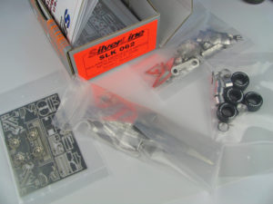
3.1 – Kit contents
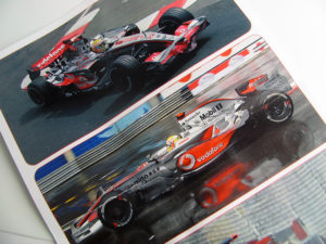
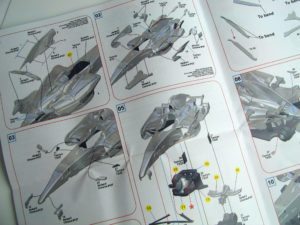
SLK 062 is fairly typical of recent Tameo/SilverLine kits. Cast metal is used to replicate major components as well as detail parts with complex (multi-dimensional) curves, turned metal parts are included for wheels and hub details, while photo-etch metal is used to replicate many of the flat and thin parts of the car. The usual full colour instruction sheet, pictures of the real car and perfectly printed decals are also included. The spread of parts for this kit clearly indicates the complexity of the design and manufacture of these cars.
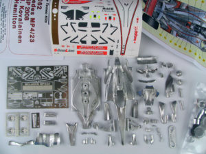
3.1 – Kit contents
Unique design features of the real car as it appeared in the Monaco GP are faithfully reproduced in cast and etched metal. The most notable of these are the treaded ‘wet’ tires for the rainy conditions during the race, but also extends to the various aerodynamic parts and high down-force wings used at this venue.
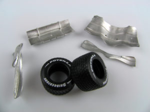
3.1 – Kit contents
The key components are test fitted to check the overall proportions of the model, become familiar with the fit of parts, and begin to plan the assembly and painting sequence.
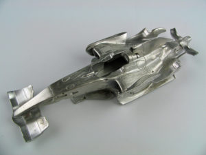
3.2 – Parts preparation
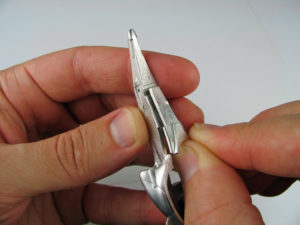
The attachment of the lower monocoque and upper body parts demonstrates the superb fit of parts that is possible with current design and casting technology.
3.2 – Parts preparation
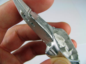
The two parts fit neatly, making the process of filling gaps and preparing for paint much easier and quicker. Similar quality fit of parts is evident with other aerodynamic elements of the model.
3.2 – Parts preparation
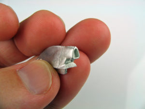
The airbox of the Mp4/23 is cast with a significant recess in the opening. Painting this black would give quite a convincing impression of depth.
3.2 – Parts preparation
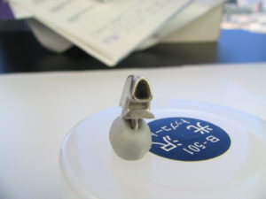
Following the techniques demonstrated in Section 2.5, the airbox was opened. With the Mp4/23, the entire airbox and spine of the engine cover is provided as a separate part and it is easiest to open the appropriate sections before adding this to the main body. The corners of the airbox opening are initially drilled out, before the remainder of the hole was opened with a file and knife. Not visible in these pictures, but a separate hole was drilled up inside the part to give the metal filings an escape path as the airbox is being opened.
3.2 – Parts preparation
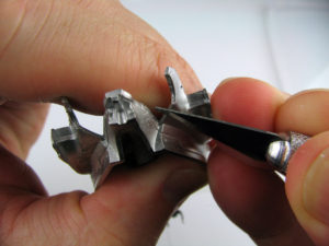
At the rear of the Mp4/23, a number of carbon fibre aerodynamic features terminate with sharp edges and corners. All of these components are faithfully reproduced in the SilverLine kit and produced as thinly as possible given the limitations of manufacturing processes and transportation. The accompanying image shows the rear of the body as provided in the kit.
3.2 – Parts preparation
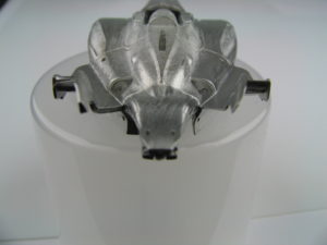
Utilising the tools and techniques from Section 2.5, these various aerodynamic details are thinned and smoothed. Particular care must be taken when using rough files and sandpaper that surrounding areas of the model are not damaged. Depending on familiarity with the tool, a dremel motor-tool can also be used to speed up the initial thinning. After a half hour of sanding and polishing with steel wool, the parts are considerably thinned
3.2 – Parts preparation
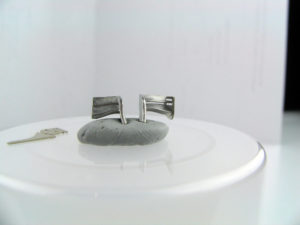
Like all Grand Rrix race cars of 2008, the McLaren featured small ‘flip up’ wings on the side of the engine cover. In the SilverLine kit, these are replicated in cast metal, with photo etch endplates. Prior to attachment of the endplate, a scribing tool was used to cut away at the gap between the main plane and the flap, until the two sections were separated. The resulting edges are sanded smooth and the parts are ready for priming. This modification is a lot of work for a very minor improvement, but it was an interesting experiment.
3.2 – Parts preparation
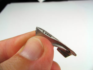
For the Monaco GP, the Mp4/23 competed with the left chimney open and the right side fully closed. In the SilverLine kit, the top of the right chimney is manufactured with a recess, with the bottom of the recess to be painted black after the body has been finished. To give a greater sense of depth, the part can be opened further. Initially a number of small holes are drilled down into the chimney as shown in the accompanying picture.
3.2 – Parts preparation
Using similar tools and techniques to the opening of the airbox, the remaining metal between the holes is progressively removed. A scribing tool and a small saw blade can be useful in opening a long thin section such as this. With the bulk of the metal removed, the sides are sanded smooth and polished with steel wool.
3.2 – Parts preparation
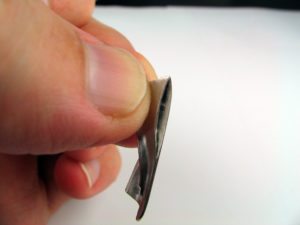
Both the front and rear wing elements are cast as groups. The edges of each element are sharply defined, however to maximise the definition, modellers may choose to scribe or cut the grooves slightly deeper. For the rear wing, these grooves were scribed until the parts were fully separated. This is shown later in Section 3.9.
3.2 – Parts preparation
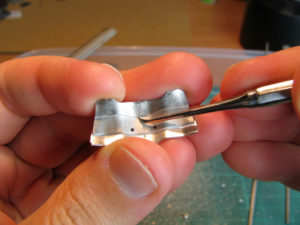
Another unique feature of recent grand prix cars is the thin bridge wings forming part of the front wing structure. The McLaren design involves a single element that loops up over the nose of the car and attaches on either side to the front endplates.
3.2 – Parts preparation
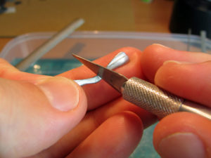
Using the techniques outlined earlier in this Section 3.2, the bridge wing is thinned closer to its scale thickness. Another feature of McLaren’s design is the split in the main ‘wing’ sections on either side. If desired, this is another area where the engraved kit detail can be accentuated by scribing the recess from both sides until the elements are separated.
3.3 – Carbon Fibre
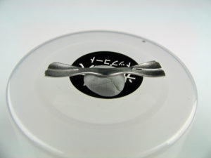
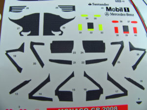
While modern cars typically feature bold and colourful livery, sections of the cars are often left in a raw carbon fibre finish. Replicating this fine weave pattern in 1/43 is an interesting challenge. These sections can be painted with semi gloss paint (either very dark grey or black), but the application of carbon fibre decal can offer the best solution if a fine enough weave pattern can be found. Tameo models typically include carbon fibre decals for many sections of the car (suspension arms, wing endplates etc) and these pre cut decals are a great solution for these areas.
3.3 – Carbon Fibre
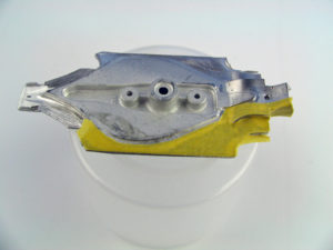
As it is not practical to include carbon decals in the kit for all relevant sections of the car, modellers must decide on how they wish to treat the remaining section. Obviously spraying with semi gloss black is the simplest solution. If decals are to be applied, the most important step is creating an accurate pattern for the area to be covered. Putting a section of masking tape onto the model and trimming to size with scissors or a sharp knife is a good way to do this. Carbon decals tend to look best if the pattern applies consistently on the model, so try to have any joins in the pattern at natural joins on the model.
3.3 – Carbon Fibre
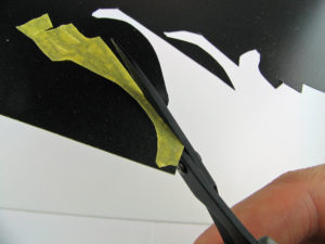
The masking tape pattern can then be struck to the decal sheet and the pattern cut out. Remember to reverse the pattern (by sticking the tape to the reverse side of the decal paper) for the opposite side of the model. Another suggestion with carbon decals is that if a particular pattern looks too bright on a model, it can be over-sprayed with clear ‘smoke’ (TS 71) to darken the colour. The decal sheet used here is from a Japanese company called Modellers. Unfortunately this company is no longer in operation, but a number of companies offer ‘fine’ or ‘very fine’ weave carbon decal. Consult your Tameo dealer for an appropriate source. Many Tameo kits include a second decal sheet and this will allow builders to quickly accumulate a collection of spare carbon decal.
3.4 – Pre-assembly
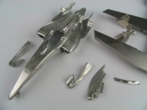
A further consideration with any model is the decision about how many parts to assemble into sub-assemblies prior to painting. To make the model easier to paint, it is usually preferable to keep parts separate and only assemble those parts where filling and sanding is required before painting.
For this McLaren, the front wing supports, airbox, chimneys and lower element of the rear wing all needed to be fitted for this purpose. To minimise handling given the delicate chrome paint surface, other parts such as wing mirrors and rear wing end plates were also added. The parts are shown in the picture prior to assembly. Note the rear wing was assembled using a calliper as shown in Section 2.6.
3.4 – Pre-assembly
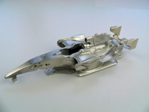
The accompanying picture shows the McLaren with all parts attached prior to painting. As the chrome surface would clearly show any imperfections, considerable time was taken to ensure a smooth transition between the airbox, chimney and wing support parts. ‘White stuff’ filler and Tamiya surface filler were both used for this purpose. To avoid damage to the smaller detail parts (rear wing and mirrors), all filling and sanding of the chimneys and airbox was completed before these parts were attached.
3.4 – Pre-assembly
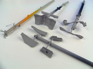
The other detail parts to be painted in chrome are all kept separate and mounted on plastic ‘trees’ for painting.
3.5 – Diffuser
Similar techniques to those described in Section 3.2 can be applied to the diffuser section at the rear of the car. This section is represented in cast metal in the kit, accurately capturing the complex design of this area.
3.5 – Diffuser
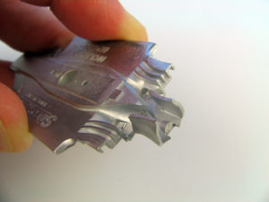
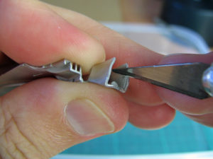
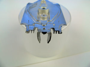
This is typically a very complex arrangement of channels and vanes, each made from carbon fibre and featuring a thin cross section. While this area of the car will ultimately be painted black and is somewhat out of sight, improving it can be satisfying and really set your model apart. The accompanying photograph shows the process of trimming away the cast metal with a knife. Once the edges are carved, a file and sandpaper are used to smooth the area, before a final polish with steel wool.
3.5 – Diffuser
The picture shows the diffuser with the left side thinned, sanded and polished and the right side unaltered. Obviously white metal cannot be cast as thin as the finished part (left side), but further refined casting in the SilverLine Renault R28 kit provides thinner parts straight from the box.
3.6 – Other sub-assemblies
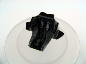
A number of other sub-assemblies can be completed in parallel with the body parts. One of the largest of these is the seat. The assembly steps are described in detail in Section 2.7, however in summary, once satisfied with the test fit of the part inside the body, the photo-etch belts can be bent to fit the curve of the seat. The seat and belts are primed and painted in gloss black. Decals are applied, before the seat is coated in semi-gloss clear and the belts with flat clear. Buckles are painted in Tamiya X10 gun metal and the belts are glued to the seat.
3.6 – Other sub-assemblies
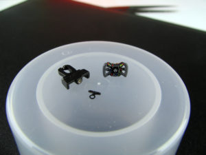
The steering wheel receives similar treatment to the seat – painted in gloss black, decaled and then sprayed with semi-gloss clear. Grips are brush painted with grey enamel.
3.6 – Other sub-assemblies
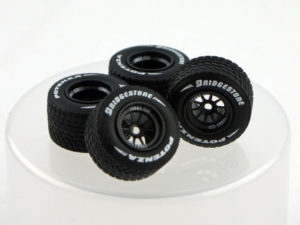
The McLaren’s wheels are replicated with turned metal rims, pressed photo-etch spokes and pre-printed rain tires. Again, the assembly steps follow those of Section 2.8. For additional visual interest, the wheels were painted with Tamiya TS 40 Metallic Black before decals and semi gloss clear.
The completed wheels and tires are shown in the accompanying picture.
3.7 – Floor and Suspension
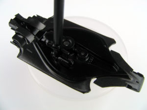
After thinning the diffuser in Section 3.5, a small nut is glued in the centre of the floor to allow attachment to a display base. The floor is then primed, painted black and the decals prepared in Section 3.3 are applied. A final coat of semi-gloss clear finishes the part.
3.7 – Floor and Suspension
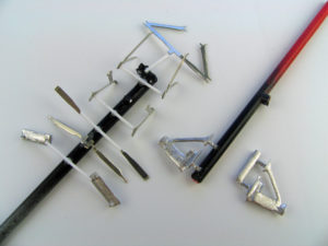
Modern Formula 1 suspension parts are primarily made from carbon fibre and have much longer, more aerodynamic profiles. The suspension parts for the Mp4/23 model remain principally made from photo-etch metal, however the front upper wishbone is cast metal to allow the profile of the arms to be more accurately portrayed. All suspension arms are filed and sanded to give a slightly rounded profile and sharp trailing edge, as demonstrated in Section 2.9. All elements are test fitted to the car and the uprights prior to painting. If a part needs to be bent (as is the case with the lower wishbone) this should be done with the etched fold line on the inside of the bend.
3.7 – Floor and Suspension
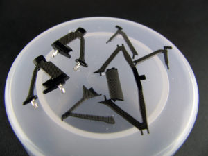
The carbon fibre decals in this kit are lighter than those included in some other kits, creating a higher contrast weave pattern. Depending on personal preference, a light over-spray with Smoke (clear grey) can darken the parts and lower the contrast. Whether or not the Smoke paint is applied, the parts can be given a final over-spray of semi-gloss clear and set aside to dry for final assembly.
3.8 – Paint
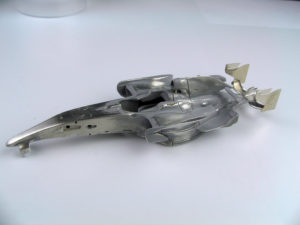
Following the techniques from Section 2.14, the body is sprayed with metal primer and then a light coat of grey primer. Any problem areas are fixed with ‘white stuff’ filler or Tamiya surfacer. Once these are fully dry, the whole body is sanded with #800 sandpaper. A final rub with steel wool across the flat, open sections of the body prepares the surface for final priming. Through these steps, it is important to avoid sanding across the raised details too frequently. Folding sandpaper in half, rolling it around the handle of a paintbrush, or sticking it to plastic card with double sided tape, can all help in reaching small recessed areas without damaging surrounding areas.
3.8 – Paint
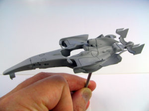
The accompanying photo shows the model after a final coat of primer has been applied. A very careful inspection of the whole body in needed to ensure that all seams are filled and the surface is smooth. Any imperfections will clearly show through the chrome paint.
3.8 – Paint
There are a number of alternatives for painting the McLaren (Alclad II, Zero chrome, Motochrome etc), but all require an airbrush to apply the paint.
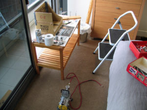
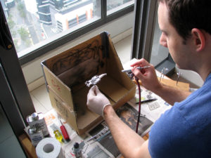
I do not have enough space at home to keep my airbrush set up permanently, so I keep all the required tools and supplies in a box and set up the airbrush whenever needed. The cardboard box ‘spray booth’ is set up in a doorway when the breeze is low, but moving in a direction that sucks the fumes out the door (sometimes I need to wait a few weeks for the right conditions..!). Otherwise the various elements of the set-up are apparent from the picture.
3.8 – Paint
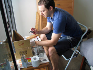
Spraying the model parts is fairly straightforward. Many airbrush colours are supplied ‘pre-thinned’, but a little experimentation will indicate the ideal thinner-paint mix for the product you are using. Always keep the coats light and carefully monitor the coverage of the part. Because a ‘double action’ airbrush allows the flow of paint to be controlled, the model can be painted from close up and the paint can be sprayed into recesses and detail areas with minimal risk of pooling. Once satisfied with the result, thinner or airbrush cleaner is put into the paint cup and blown through the airbrush to clean it for the next use.
3.8 – Paint
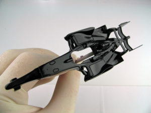
The ‘prismatic’ chrome paint requires a high-gloss black undercoat. The Zero Paint package used for this build provides a flat black undercoat and then a gloss clear overcoat to achieve this effect.
3.8 – Paint
McLaren’s chrome silver finish is one of the more challenging colours to replicate in miniature. Most chrome paints (Alclad II and similar) are fairly fragile and likely to be damaged by further painting (including clear), the application of decals, or masking tape. Although its tone is slightly too light for the Mp4/23, Zero Paints’ McLaren chrome was used as it is reasonably resilient to subsequent clear-coating and handling. 2-3 extremely light mist coats achieve the desired effect. For modeller without an airbrush, Tamiya’s TS83 over gloss black would be a reasonable alternative although this paint cannot be clear-coated.
3.8 – Paint
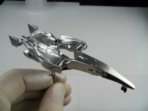
The completed chrome finish is a reasonable match to the real Mp4/23. A light clear coat was sprayed as preparation for masking off the red section on the spine of the car.
3.8 – Paint
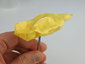
Completing the McLaren colour scheme requires the painting of a thin red stripe down the spine of the engine cover. Thankfully a decal is provided for the black demarcation line and this is useful for cutting the masking tape to the correct shape. The decal sheet is photocopied and the paper copy is cut along the middle of the black decal shape to make a template. Masking tape is then stuck to the paper section representing the shape of red section needed on the car. The overhanging tape is then cut away. This ‘overhanging tape’ is the shape of the silver edge and can be placed straight onto the model. With the edge defined, the rest of the body can be carefully masked.
3.8 – Paint
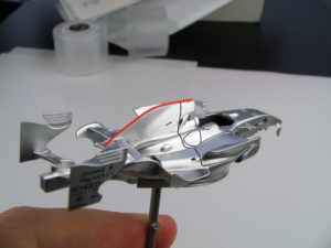
A light undercoat of white primer was sprayed over the model to neutralise the silver before two light coats of fluorescent red. The mask was not perfectly clean, but this is no problem as the line is covered by a black decal anyway. Gloss clear was sprayed along the red paint and sanded back to assist in blending the ‘step’ between the silver and red colours.
3.9 – Other body parts
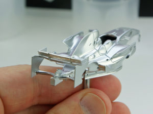
As shown in Section 3.2, a scriber can be used to deepen the detail between wing elements. To demonstrate the detailing possibilities in 1/43, the rear wing elements were completely separated on this model. This was achieved with repeated scribing and cutting from both sides until the opening met in the middle. Thin strips of sandpaper were passed through the gaps to remove any rough edges. Time-consuming but satisfying! The wing element was then test fitted between the endplates to ensure it can easily be added after painting. It is advisable to allow a slightly loose fit as the paint and decals will ensure a tighter fit at final assembly.
3.9 – Other body parts
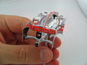
The rear wing is then separately painted in fluorescent red, decaled and clear coated. The black decal for the leading edge of the wing was cut into three sections to fit between the two wing stiffeners. The dividing ridges were hand-painted after application. Once painting is complete, the wing elements can be gently fitted back between the endplates. It may be necessary to sand the paint from either end of the wing elements to ensure the part will fit. Once in place, a tiny amount of superglue can be dabbed on the underside of the join to secure the part.
3.9 – Other body parts
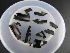
Following the techniques described in Section 3.3, surplus carbon fibre decal can be used to cover various small detail parts. A collection of these are shown in the accompanying picture. Depending on preference, a similar appearance can be achieved with semi-gloss black paint as suggested in the instructions.
3.10 – Decals
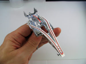
In combination with their sculpted, purposeful designs, the unique and colourful liveries are a significant part of the modelling appeal of racing cars. As demonstrated in Section 2, Ferrari grand prix cars are typically very simple to decorate, however most other teams feature more complex, multicoloured schemes. The Mp4/23 is largely silver, but does have large sections of red for its sponsor ‘Vodafone’, as well as black demarcation lines between the red and silver. Positioning these large decals is a time-consuming exercise, but is perhaps one of the most satisfying parts of the entire build process.
3.10 – Decals
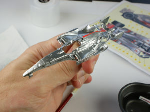
Having considered the various decals to be applied and determined the preferred order of application, its time to get started. The most important step in applying large markings is to allow sufficient time to correctly position the decal before it bonds with the model. As shown in the accompanying picture, drops of filtered water can be positioned in the area where the decal will be applied. This will slow the drying of the decal glue. Once the decal is correctly positioned, this water can be brushed out from under the marking with a soft paint brush. During this phase, it is important to continually check the position of the marking from all angles and compare to reference pictures. Softener can be used where needed to ensure the decal conforms.
3.10 – Decals
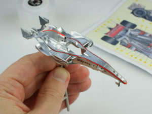
With the major markings applied, the smaller sponsor logos can be applied. Suddenly the model starts to look much more like the real car.
Once all decals are applied, the model can be clear coated as described in Section 2.16 and set aside to dry fully before final assembly.
3.11 – Detail parts
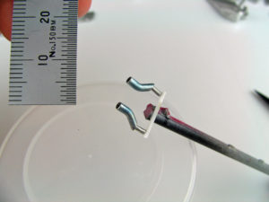
The Mp4/23’s uprights and brakes are provided as single cast metal parts. The cooling ducts were drilled out with a pin vice and file. Small photo-etch tabs are provided for the lower inside of the front uprights. These are curled by rolling them around a metal file handle. To contrast with the carbon decaled suspension wishbones, the uprights were painted in semi-gloss black. If desired, these parts could be covered in carbon weave decal.
3.11 – Detail parts
The exhaust pipe parts are lightly sanded and polished with steel wool to ensure a smooth surface. When sanding round objects, wrap sandpaper around the part and twist the part inside the abrasive so pressure is applied evenly from all angles. The smoothed pipe can be polished with Tamiya polishing compound to bring it to a high gloss finish. A pin-vice is used to drill out the end of the pipe. Depending on preference, the modeller may choose to apply slight discoloration to the exhaust. This can be done with very heavily diluted clear colours (smoke, green, blue and purple etc) or with Tamiya’s weathering kit as in this case.
3.11 – Detail parts
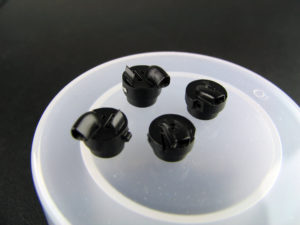
As with many of the other detail parts, the camera pod is painted black and decaled with the markings provided in the kit.
3.12 – Final assembly
With all painting now complete, the dashboard, seat and steering wheel (in that order) can be installed into the monocoque. It is easiest to hold the model upside down when installing the dashboard and seat. The parts are carefully set in place then small amounts of superglue are dotted along the join. These parts are not weight bearing, so only a tiny amount of glue is needed to hold them in place.
3.12 – Final assembly
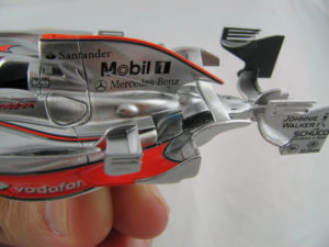
Flat black is brush-painted in the area where the exhausts protrude. This section is largely hidden once the pipes are in place, but the paint helps to add shadow and depth. The heat shields under the pipes were painted in flat aluminium to contrast the surrounding chrome. Finally the exhaust pipe sections are fitted in place with a small amount of superglue.
3.12 – Final assembly
The front lower wishbone was fitted next. This part is flexed slightly so the mounting pins can be slipped into the holes drilled in the side of the body. A tiny amount of extra thin superglue can be touched to the lowered side of the attachment points. The glue will naturally be drawn into the attachment point and will secure the part in place.
3.12 – Final assembly
The Mp4/23 includes several vertical aerodynamic attachments between the floor and the body. To correctly position these, the body is placed on (but not attached to) the floor. Sitting the model on a stable surface, the body can be lifted a millimetre or two and each of the parts inserted one by one. Once correctly positioned (and with the body sitting flat and square on the floor part), tiny amounts of superglue can be flowed on the inside attachment of the vertical parts and the floor. This glue will be out of sight once the model is assembled. In the accompanying picture, the body has been lifted from the floor to show the attached parts. Once this process is complete, the body and floor are secured together with a screw.
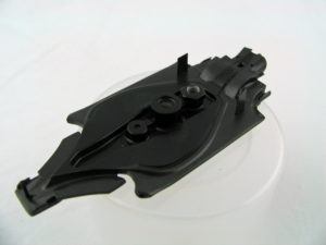
3.12 – Final assembly
Suspension and uprights are next to be added to the model. This process largely follows the instructions, but it is important to carefully test fit all parts and the assembly sequence. At the rear, the lower wishbone and upright are added, ride height checked (see Section 2.17) and the suspension pushrod attached to fix the height. Next the drive shaft is shortened to length and fitted. The track rod and upper wishbone complete the assembly. To secure the parts, small ‘dots’ of superglue are applied in areas that are not visible on the finished model. At the front, the proximity of the upper wishbone and suspension pushrod mean both these parts should all be fitted to the car before the upright is attached.
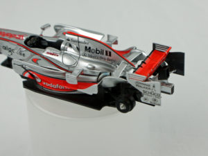
3.12 – Final assembly
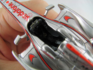
Various other aerodynamic attachments, as well as the camera pod, are added with small ‘dots’ of superglue. Some modellers may prefer two-component glue as it allows more time for the parts to be positioned and avoids the risk of ‘frosting’, however if only small amounts of superglue are used, ‘frosting’ is not a significant problem. Personally, I’m just too lazy to mix up two-component glue for these small attachments. The inside of the airbox is also painted. A thin strip of carbon decal is looped inside the opening to give a sharp edge to the black interior.
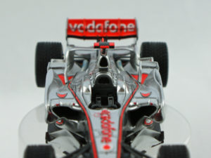
3.12 – Final assembly
The McLaren’s bargeboards are next and if the instructions are followed closely, attaching them is a fairly straightforward exercise. After the contact point is cleaned of paint, the photo-etch base plate is glued to the bottom of the main bargeboard. Depending on preference, the small carbon fins can be attached before or after the bargeboard is attached to the body. In the picture, one final carbon part is missing from the rear of the bargeboards. This was attached last to ensure it was parallel with the ground. Remember to fit the upper front attachment point to the monocoque as this must be sandwiched between the bargeboard and body.
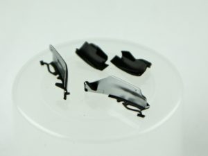
3.12 – Final assembly
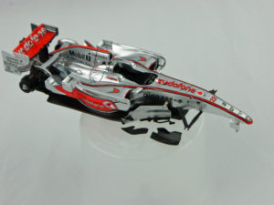
The primary attachment point for the forward bargeboards is on the side of the monocoque, in amongst the lower wishbone, however the part is also supported by the photo-etch base plate. Although thin in sections, this assembly is actually very strong.
3.12 – Final assembly
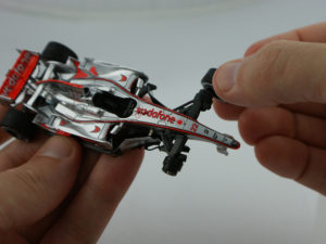
Wheels are then attached following the approach detailed in Section 2.17. So long as the uprights/hubs are mounted squarely, this should be a fairly quick exercise.
3.12 – Final assembly
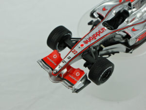
The front wing must be assembled in a careful sequence to ensure the finished part is symmetrical. Because the bridge wing curves tightly up over the nose, it might be difficult to attach the wing if fully assembled before attachment. As an alternative, the main wing elements and one endplate are attached to the nose as shown in the accompanying picture. The bridge wing is then placed in position, against the attached endplate. Finally, the second endplate is attached, ‘sandwiching’ the bridge wing in position. Two-part glue is good for this type of application as it allows more time to position the parts before curing.
3.12 – Final assembly
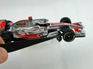
Turned metal wheel nuts are provided in the kit. These can be fixed in position with superglue. The front wheel covers are then attached. Pay particular attention to the position of the open section as these disks do not rotate with the wheels.
3.12 – Final assembly
The inside of the chimney opening was painted black, aerial and pitot tube parts added on top of the monocoque, and the model is complete !!
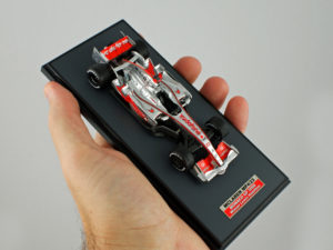
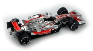
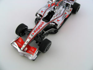
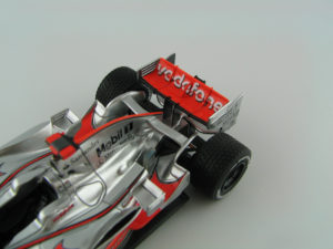
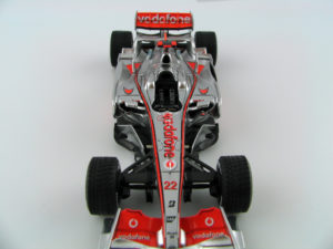
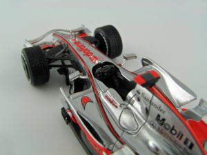
The nameplate is included in the kit. The following photographs were taken inside a light tent.
