Pick a language
Tutorial
Section 2 – First Built (edited by Michael Kelly)
This section will provide a detailed, step-by-step guide to the assembly of a 1/43 Tameo Kit. A recent Tameo release, the Ferrari F189 as raced at the 1989 Hungarian GP (TMK 371), will be featured. As outlined in Section 1.1, for fans of other grand prix teams, the techniques described here can be applied to the wide variety of models in the Tameo Kits range. This particular car was selected because it is a recent Tameo Kits release featuring the latest in design and casting technology, was a race winning and historically significant design, with few aerodynamic attachments and simple livery. All features that make it an excellent project for a beginner to 1/43 scale models.
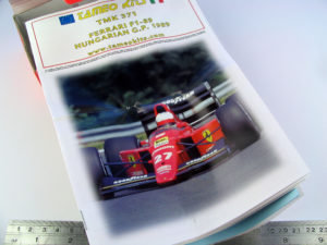
TMK 371 is a modernised kit of a vehicle which was first modelled by Tameo Kits when the car was competing in 1989. The new model features cutting edge design and manufacturing technology, has excellent detail and due to the precision of the design, is easy to assemble. As with most 1/43 scale kits, this is a curbside (no engine detail) model, making assembly an easier proposition. The Brazilian GP version of the F189 was the subject of a recent Tameo built release (TB 004) which is now sold out. This kit provides collectors an opportunity to add this different variant to their collections.
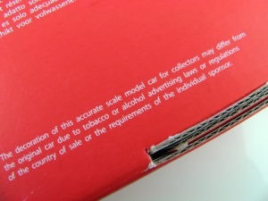
In compliance with company policy and applicable law provisions, the scale car model featured in this build manual does not bear any decals and stickers reproducing logos and brands owned by tobacco producers.
Please contact your Tameo Kits dealer if you have any questions about this policy.
2.1 – Checking kit contents
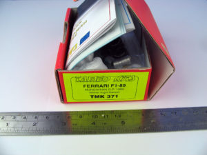
Tameo kits arrive neatly bagged and packed inside a small but sturdy cardboard box.
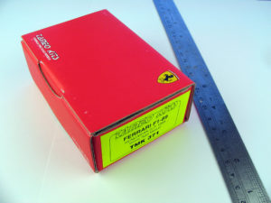
2.1 – Checking kit contents
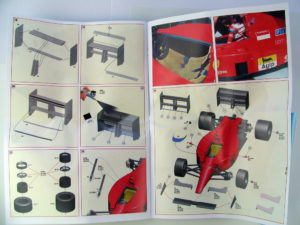
Full colour instruction booklet and reference photographs are included in most kits. Older kits feature simpler, line drawing instructions
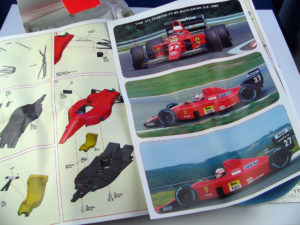
2.1 – Checking kit contents
Given the small scale, decals are extremely important to a 1/43 model and Tameo Kits provide very high quality transfers for much of the decoration of the model. Accurate colours, sharp printing and often a full set of templated carbon fibre decals, add greatly to the appearance of the finished model. In kits numbered TMK193 and above, two decal sheets are included in the box.
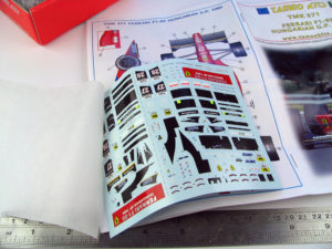
2.1 – Checking kit contents
Parts are separated grouped and sealed in small plastic bags.
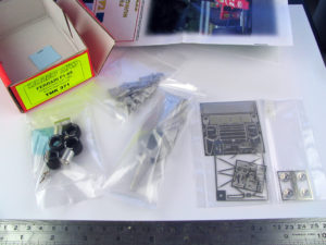
2.1 – Checking kit contents
After opening the plastic bags, all parts should be laid out and inspected for damage. All kits will have some minor surface imperfections from the moulding process however these are easily remedied during assembly, as outlined in this manual. Tameo have extremely effective quality control systems and it is extremely rare for parts to be missing, however should something be missing or damaged, please contact your distributor for a replacement. Smaller items such as axles and wheel nuts may be best left in the plastic bag until needed to reduce risk of parts being lost.
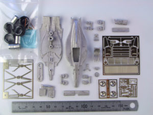
2.1 – Checking kit contents
Before starting on the build, the instructions should be reviewed in detail. These will identify the correct assembly sequence, but the modeller needs to also consider whether parts should be assembled before or after painting and the extent of any preparatory work required. These steps may be slightly different for different models, but the general theme is to group similar colours for ease of painting. A further consideration in planning the build sequence is to identify those sections where decals need to be applied. Decals adhere much better to gloss surfaces, so a section needing decaling should be painted in gloss paints and then sprayed with clear if a semi-gloss or flat finish is required. The steps in this build manual highlight areas where this is a consideration.
2.2 – Preparing cast metal parts
With the kit and tools ready to go, and the build steps planned out, its time to get started! The first step is to clean up any moulding scars on the cast metal parts and prepare them for painting. The casting on this kit is of a very high quality, but as with any casting process, there are sections on each part that carry some residual pitting or mould separation lines.
2.2 – Preparing cast metal parts
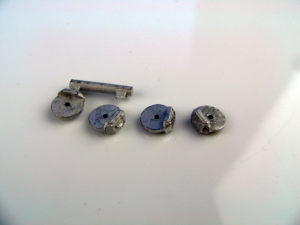
Smaller white metal parts are often cast on ‘trees’ to improve the efficiency of the moulding process. These parts must be separated and cleaned up prior to painting. Pay particular attention to the instruction sheet to understand how parts are designed to fit together. Sometimes a stub on a part can actually be an important locating point for attachment to other parts of the kit rather than a remnant from the moulding process.
2.2 – Preparing cast metal parts
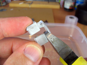
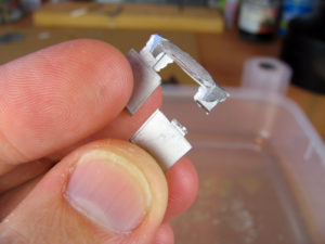
Parts are clipped from the moulding tree with side cutters. Care must be taken not to damage the actual part. If in any doubt, cut further away from the part as it is always easier to return later and shave more from the part than it is to repair a damaged piece.
2.2 – Preparing cast metal parts
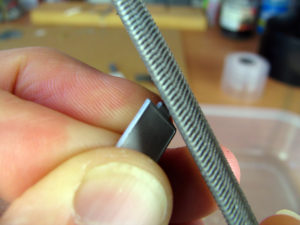
A rough file may be used to quickly remove the bulk of the moulding stub.
2.2 – Preparing cast metal parts
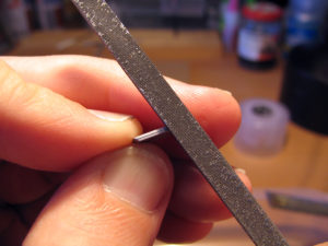
Finally a fine/light file and sandpaper is used to smooth the last of the moulding stub.
2.2 – Preparing cast metal parts
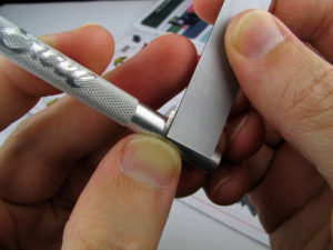
As an alternative, a hobby knife can be used to shave off small imperfections and mould seams. This is easiest done by sliding the knife blade sideways along the surface of the metal.
Sandpaper of varying grades is also useful in this process – especially for sections of the part where it is difficult to use a file. Spare sections of cast metal ‘tree’ can be useful for practicing techniques to remove and smooth the metal.
2.2 – Preparing cast metal parts
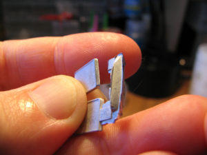
The accompanying photo shows the cleaned up radiator parts test fitted inside the body of the car.
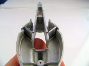
2.2 – Preparing cast metal parts
Some parts may carry minor pitting on the surface. If the pitting is significant, the affected area should be filled with putty or surface filler, however for most minor pitting, it may be easiest to fill the imperfections with surface filler after the first primer coat has been applied.
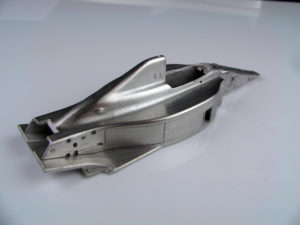
2.3 – Photo-etch parts
As with the cast metal pieces discussed in 2.2, photo-etch metal parts require some specific techniques to ensure they look their best.
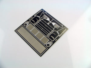
2.3 – Photo-etch parts
Most photo-etch parts are made using a two phase chemical etching process that allows parts to be made with some detail etched half way through the sheet of metal, and other patterns etched completely through. This allows fold lines and other detail to be etched into the surface of the parts.
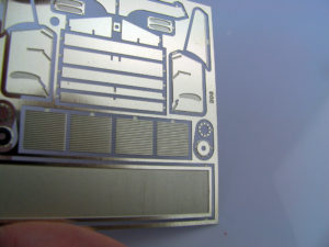
2.3 – Photo-etch parts
Scissors are the preferred tool for removing the photo-etch parts from the frame (fret) that hold them. Over time, this process will blunt the scissors, so it may be preferable to identify a pair of scissors specific for this purpose.
Start by cutting the surrounding frame away with side cutters. This allows easy access to the actual attachment point.
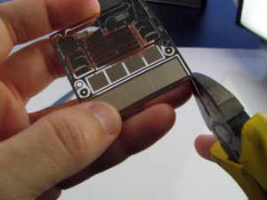
2.3 – Photo-etch parts
For a right handed person, the parts are most easily cut with the part in your left hand and the fret being removed to the right. The scissors are pressed up against the part as shown in the picture and the excess metal is snipped away.
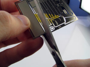
2.3 – Photo-etch parts
To prevent pressure from the scissors distorting or curling the actual part, it is best to hold the part parallel to the lower scissor blade during cutting. This is demonstrated in the accompanying photo, however modellers who are new to this technique can practice cutting the attachment points where they meet the fret rather than the actual parts until comfortable with the approach.
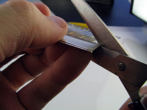
2.3 – Photo-etch parts
Working around the part in a counter-clockwise fashion, the part is progressively removed from the fret. In some cases, excess sections of the fret must be cut with side cutters to provide access to the part.
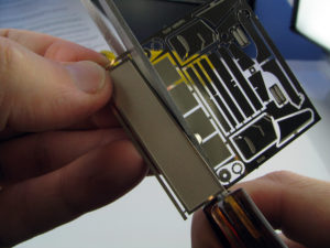
2.3 – Photo-etch parts
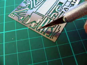
In some cases where accessing the attachment point is difficult, the part must be cut free with a knife and tidied up with scissors or a file later.
2.3 – Photo-etch parts
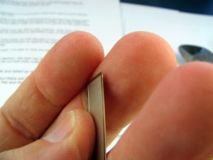
With practice, the scissors will give a very neat cut, but there will always be a minor difference between the area where the part was attached to the fret and the surrounding section.
2.3 – Photo-etch parts
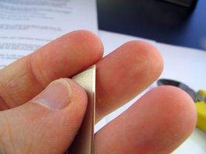
These areas can be easily filed smooth.
2.3 – Photo-etch parts
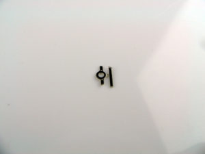
For some smaller parts, or parts that need to be painted entirely in a single colour, it may be preferable to leave a small section of fret so the part can be attached to a handle for painting. The etched metal attachment will always be more durable than attaching the part to wire or plastic with glue.
2.3 – Photo-etch parts
Some photo-etch parts will need to be bent prior to use. If a sharp, straight bend is required, the part will typically be made with a fold line etched into its surface. These fold lines create a natural point of weakness and the bend will tend to occur where intended, however to avoid bending the surrounding parts, it is best to hold the part as close as possible to the fold line and apply even pressure along the fold.
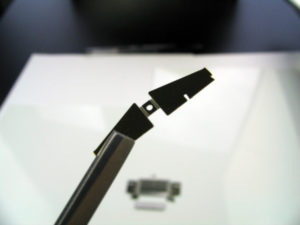
2.3 – Photo-etch parts
This can be done with tweezers.
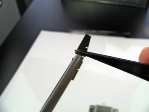
2.3 – Photo-etch parts
… or tweezers and a ruler for a longer fold
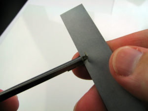
2.3 – Photo-etch parts
For a very long fold, it may be necessary to use two rulers (as demonstrated here), or a purpose build tool such as an “Etch-Mate”. The aim is to focus the pressure of the bend directly and evenly along the fold line to ensure the surrounding parts remain square and flat. These longer folds are rarely required on standard kits, but a part from the Tameo Lotus 56B superkit is used here to demonstrate the technique.
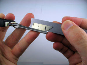
2.3 – Photo-etch parts
If the photo-etch part need to be curved, it can be helpful to bend the part against an object with similar radius to the curve required. This may be a spray can, a tool handle, or for tight bends, a drill bit. A part from the Tameo F187 (TMK376) is used here to demonstrate the technique.
2.4 – Test fitting cast parts
The two largest parts in most Tameo models are the body and the floor.
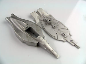
2.4 – Test fitting cast parts
Obtaining a good fit between these parts is important to ensure the finished model will sit square on its wheels and also to avoid any gaps being visible between the parts.
2.4 – Test fitting cast parts
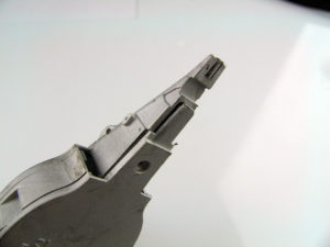
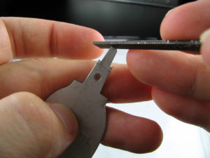
Any mould seams along the contact points between the upper body and the floor should be filed smooth to ensure a clean fit.
2.4 – Test fitting cast parts
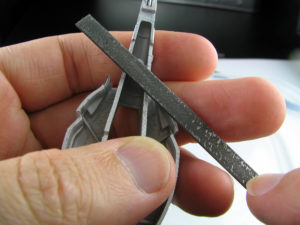
The corresponding sections of the floor are also filed and sanded to ensure the match correctly to the body. During this process, constantly test-fit the two parts to ensure that they align as intended, and to avoid filing away too much of the parts.
2.4 – Test fitting cast parts
Following removal of the moulding flash the parts will generally fit together well. Any misalignment should be evident at this time and can be corrected by shaving or sanding the metal in the relevant area.
2.4 – Test fitting cast parts
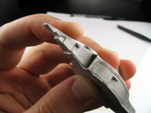
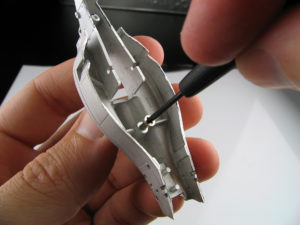
To ensure a strong connection between the body and floor, Tameo Kits provide a small self tapping screw to join the pieces. As some force can be required to insert this screw, it is best to drill a hole and insert then remove the screw a couple of times prior to any painting so it can be added easily after assembly. Wetting the thread of the screw can help it cut into the metal the first time.
2.4 – Test fitting cast parts
In screwing the body and floor together, it may be apparent that the floor has warped slightly during delivery and handling. As the metal is slightly pliable, it is possible to slightly bend the floor to return it to correct alignment with the body.
The floor should connect with the body in such a way that the screw area is the last to touch. This means that as the screw is tightened, it will pull the parts into firm contact.With the body and floor screwed together, any areas of minor misalignment can be sanded to ensure the parts line up after painting.
2.4 – Test fitting cast parts
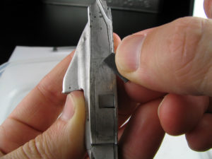
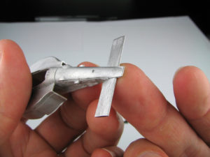
During this process, a number of other components are test-fitted to the body. The seat and the front wing (shown in the accompanying picture) are checked to ensure a good fit with the body parts. At this stage the fit should be very slightly loose to allow for the build-up of paint and decals prior to final assembly.
2.4 – Test fitting cast parts
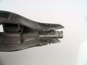
A similar process is followed with the transmission part.
2.5 – Thinning parts
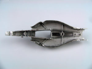
By their very nature, race cars include many thin parts and sharp edges. Replicating these in miniature is an important part of building an accurate model but can be a challenge in smaller scales. A part that is 2mm or 3mm thick on the full sized car, will be less than 0.1mm thick in 1/43. The design team at Tameo Kits seek to portray these parts as accurately as possible, however to allow the white metal to flow freely within the mould and ensure consistent casting quality, the parts are generally designed with slightly thicker edges. These kits parts look very convincing, however thinning the parts in some areas can be a satisfying exercise.
2.5 – Thinning parts
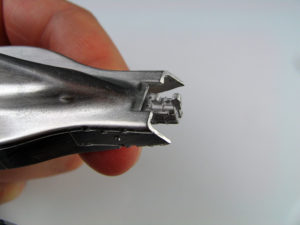
On the F189, the main area where the edges of body panels are visible is at the rear of the car. On the real car, these sections are carbon fibre sheet and would be no more than a couple of millimetres thick. Replicating this in miniature will require a little of the kit part to be shaved away. This work may be time-consuming, but looking at a finished model and appreciating the improvements can be very satisfying. The steps demonstrated in this section 2.6 are entirely optional. For a first build, a modeller may wish to proceed direct to painting however the description is provided here for completeness. As a first step, the end of the part is lightly filed to square the end, sharpen the edges and make the thickness of the part easier to see.
2.5 – Thinning parts
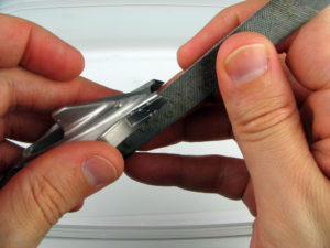
To maintain the overall dimensions and shape of the model, parts should always be thinned from the inside. A rough file can be used to quickly cut away much of the metal. Always work with the file close to parallel with the body parts and regularly
check the thickness of the edge to ensure that the filing is even and the part is not being thinned too aggressively. The aim is to reduce about 50% – 70% of the thickness of the part – enough to improve its appearance, but not so much as to significantly compromise its strength.
2.5 – Thinning parts
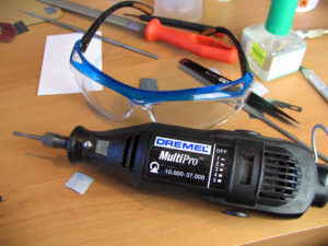
As an alternative, a Dremel or other cutting tool can be used to quickly remove sections of the kit parts. However given the metal is rather soft, extreme caution should be exercised in using this approach and it is recommended for experienced modellers only. Appropriate safety equipment should always be worn when using power tools.
2.5 – Thinning parts
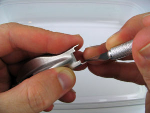
With the main filing completed, the edge can be further thinned with a hobby knife and a fine tooth file. As with the previous step, always remove the metal in small layers and regularly check the thickness. The cast metal will hold a sharp edge if treated with care, but if it is thinned too much, it will become soft. Before undertaking this work for the first time, it is advisable to practice on a spare section of metal ‘tree’ to gain confidence with the behaviour of the material.
2.5 – Thinning parts
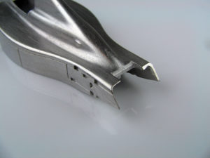
Once the part is close to the desired thickness, any minor variations can be corrected with sandpaper. Steel wool is used to smooth the edges and ensure a good surface for painting. The accompanying photo shows the rear of the body halfway through the thinning process. At left, the part has been thinned; the right is still to be worked on.
2.5 – Thinning parts
Shifting focus to the right side of the body, the metal is first thinned with the heavy file.
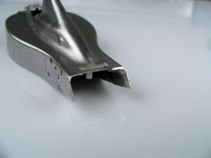
2.5 – Thinning parts
After smoothing with the fine file and some sandpaper, this section of the model is ready for paint.
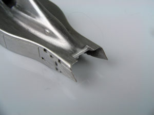
2.5 – Thinning parts
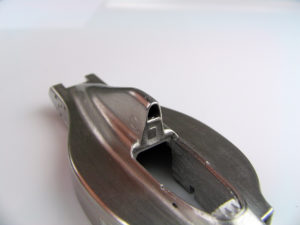
Another area of the model where builders may choose to make some modifications is the airbox. The kit part is cast with a hollowed out section to portray the opening and a black decal to give the impression of depth.
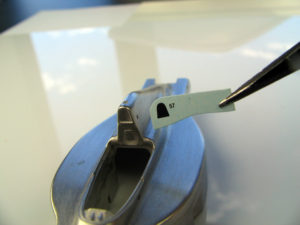
2.5 – Thinning parts
Opening this section of the model is easiest done with a pin-vice and various sized drill bits. The corners of the opening are initially drilled out to define the boundaries of the opening. The diagram shows the approach, with the numbers indicating the order for drilling the holes. The size of drill bits will differ for every car, but for this model, the lower corners were drilled with a 0.6mm bit and the top with a 1.5mm bit.
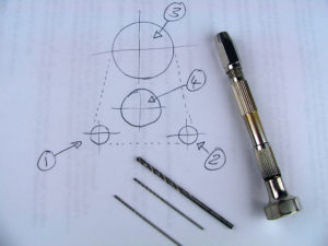
2.5 – Thinning parts
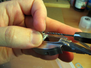
Holding the model by hand, the holes are carefully drilling into the airbox with a pin-vice. It is important to ensure that all holes are drilled square to avoid the drill cutting out through the side of the model. Depending on the shape of the car, aim to drill each hole about 8mm – 10mm deep.
2.5 – Thinning parts
The accompanying photo shows the model after the first three holes have been drilled.
2.5 – Thinning parts
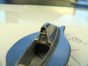
The airbox after all holes have been drilled.
2.5 – Thinning parts
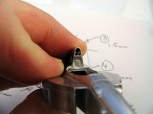
A combination of different sized drill bits, a file and hobby knife are used to merge the holes together and complete the opening.
2.5 – Thinning parts
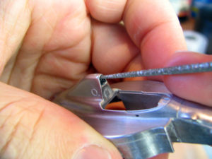
With the opening broadly complete, sandpaper, a knife and steel wool are used to tidy up the edges. After body painting, the opening can be painted in matt black to further increase the impression of depth.
2.5 – Thinning parts
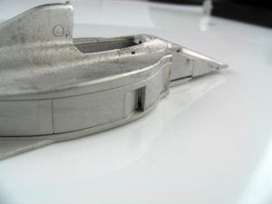
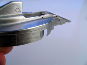
One final area of the main body part where a carbon fibre edge is visible is the vent for hot air exiting the radiators.
2.5 – Thinning parts
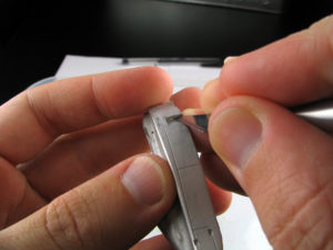
Following the same techniques as already described, the inside of these sections are shaved with a knife, sanded and then polished with steel wool.
2.5 – Thinning parts
Once finished, the edge of the vent is very close to scale thickness. More extensive thinning of parts and techniques to open NACA ducts and other openings, will be described in later Sections.
2.6 – Rear Wing
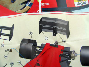
A unique and highly visible feature of Formula 1 cars since the late 60’s are the large aerodynamic wings mounted on the cars. As design rules have evolved and the overall dimensions have been constrained, the wing increasingly forms a box of thin elements or slats.
2.6 – Rear Wing
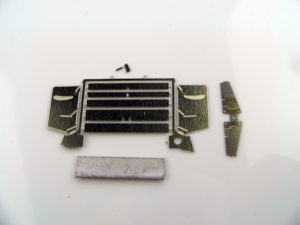
Photo-etch metal provides the perfect medium for representing the multiple elements of the F189 wing structure. Because of the importance of keeping all parts square, the assembly of these wings can be a little challenging, however with a methodical approach, a highly accurate result can be achieved.
2.6 – Rear Wing
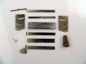
The rear wing endplates include etched locating slots for each of the components. Assembling the wing involves progressively adding the core elements (typically any cast metal parts and endplates) to form the base structure of the wing and subsequently adding the smaller parts. Check the locating slots on the inside of the endplate and determine which elements can be easily slid into place after painting. To ease painting/decaling, these parts will be painted separately. The upper edges of the various etched elements can be filed slightly to give a sharper edge if desired. Small tabs of the photo-etch frame remain on these parts so they can be easily glued to a painting handle.
2.6 – Rear Wing
Keeping the endplates square and all the elements parallel is the biggest challenge with the rear wing. With practice, a convincing result can be achieved by simply holding the parts in your fingers and ensuring they are aligned while the glue dries.
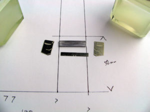
A more accurate method (that does not require specialist tools) is to draw two parallel lines on a sheet of paper and use this as a guide. Keep all lines parallel to the sides of the page to ensure everything is square. The main element and the endplates can then be positioned on the template.
2.6 – Rear Wing
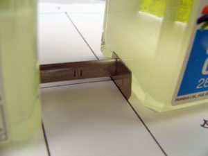
The endplates can be propped up against two square solid objects (like resting a bicycle against a wall) and the element can be lowered into place between them. In this example, two paint jars are used. Once the cast metal part is at the correct height, the bottles can be squeezed together to sandwich the part in its etched ‘slot’. Maintaining inward pressure to ensure the element stays in place, the paint jars can be moved to position the parts in line with the template. Once everything is square, the wing can be glued with superglue.
Keeping the back of the endplates resting on the flat surface ensures they remain parallel.
2.6 – Rear Wing
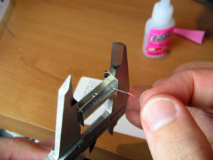
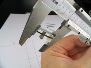
An alternative that can give perfect results is to sandwich the two endplates together and attach them to a tool that allows them to be parted in a parallel manner. A measuring calliper can by used for this purpose, or Little Cars (a Tameo distributor) offers a simple custom designed tool which operates on a similar principle.
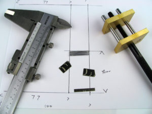
2.6 – Rear Wing
Using this approach, the endplates can be aligned perfectly and held in the closed calliper. A latex or wood glue (in this case, ‘liquid mask’), is used to tack the parts in place. This glue is used as it provides a low level of adhesion and is easy to remove when needed.
It is important to note which elements will be added so when the calliper presses the parts together, the endplates press evenly on the inserted elements. Once the liquid mask is dry, the endplates are separated.
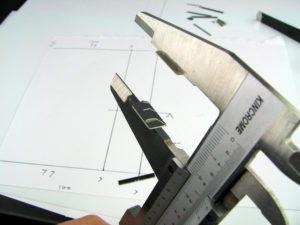
2.6 – Rear Wing
Getting more than one element in place using the method is a little difficult, so for a first build, it may be easier to focus on just the larger, white metal part. Adding the two main elements is demonstrated here for completeness. Hold the wing in such a way that the white metal part is perfectly vertical. Locate the appropriate etched slot in the inside of the endplate and place the lower end of the element into it. Use the calliper to gently bring the parts together until the element touches the upper plate. Adjust the alignment so it matches the etched indent in the upper endplate and then push the plates firmly together. The combination of the indents and friction should hold the cast metal part in place for gluing.
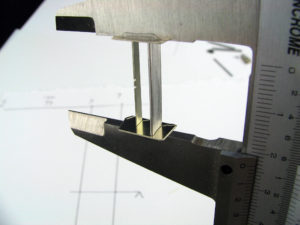
2.6 – Rear Wing
With the endplates pressed against the element, thin superglue is flowed into the join to give a firm bond. Two-component glue will give a stronger bond, but because it is thicker, it needs to be applied to the endplate parts before any element is inserted and the parts pressed together. For some builders (myself included) it is easier to ensure all parts are perfectly aligned before any glue is applied. Glue one element (in this case the cast metal part) first and then ensure that any other elements are perfectly aligned/parallel. Check this from every angle and then glue the second part.
2.6 – Rear Wing
With the basic structure in place, other elements of the wing can be added. Given all other wing flaps can by slotted into place after painting, the only extra part added was the folded central wing support. The top of this part was set in the locating slots in the underside of the cast metal element and then pushed into place. The horizontal etched element needed to be flexed a little to allow the part to snap into place. As is common with recent Tameo Kits, the fit is so good that glue is hardly necessary, but a little thin superglue was flowed into the join to sure it up.
2.6 – Rear Wing
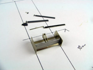
With the main parts added, the liquid mask was peeled away with tweezers and the wing removed. A feature of recent Tameo models has been to design one or more of the wing elements to slide into place through the side of the end plates. Earlier models had this element sliding in from the rear like the very top element. The new approach requires a little extra filling, but ensures that no etched slots are visible on the inside of the endplate after completion. This one final element was added so any gaps around the fitting slots in the endplate could be filled using superglue or filler, and sanded before painting.
2.6 – Rear Wing
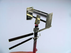
The assembled wing structure was glued to a short section of plastic rod to hold the part for painting. Superglue was used to attach the part as it gives a strong yet brittle join, allowing the part to be snapped off after painting.
Those elements to be added after painting, are also attached to the same rod with superglue. With the parts grouped in this way, they can be painted and decaled at the same time, ensuring a consistent finish across all parts.
Painting and decaling of these parts will be covered in Section 2.15
2.6 – Front Wing
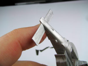
Moving to the front wing, it is very important to ensure a clean and square attachment to the main body. Starting with the main cast element, the underside of the nose is filed until a good fit is achieved between these parts. Checking the wing fits perfectly square is very important as it will be much more difficult to amend the fit of parts once paint and decals have been applied.
2.6 – Front Wing
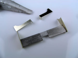
With a good fit to the main body, the remainder of the front wing assembly process is similar to the rear wing. Parts were sanded and filed to remove mould seams and slightly round the front of the photo-etch wing elements. The endplates were fixed to callipers to keep them square and parallel as the main element is glued in place.
2.6 – Front Wing
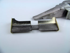
The upper elements of the front wing must be sandwiched between the painted body and the endplates, however the upper element include a small tab allowing them to be glued to the main cast metal part of the front wing. These elements were added and the complete front wing attached to a plastic rod for painting.
2.7 – Cockpit Parts
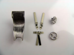
In a Tameo Kit, the cockpit is represented by a range of parts that require separate preparation before being installed into the main body part. Cast metal and photo-etch parts are cleaned and prepared as described in sections 2.2 and 2.3.
2.7 – Cockpit Parts
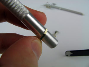
One section that requires particular attention is the seat belts. These are photo-etch parts and they must be curved to fit the seat before painting. To start, the lower sections of the belts are curled around an appropriately sized metal rod (in this case a knife handle). The part will naturally tend to bend at the sections where detail has been etched into the metal, leaving a thin section in the part. If desired, tweezers can be used to force a bend in the thicker sections of the belt.
2.7 – Cockpit Parts
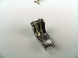
Constantly checking against the shape of the seat, the belts are further bent with tweezers, or by hand, to fit the seat. The intended length of the belt is confirmed and a sharp fold is made in line with the upper edge of the seat. The upper ends of the belts need to fit into a photo-etch panel behind the seat. The fit of these parts should be confirmed before painting starts.
2.7 – Cockpit Parts
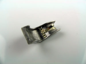
Lap belts can be similarly fitted. This part is bent in such a way that it aligns with the holes cast in the seat part, while still allowing the belt to be easily attached to the seat after painting.
2.7 – Cockpit Parts
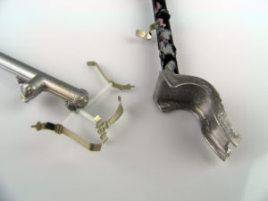
Once all parts are prepared, they can be mounted on short sticks of plastic and grouped by colour for painting.
2.7 – Cockpit Parts
As decals must be applied to a number of the parts, these are painted in gloss colours to allow the decals to adhere. Once the markings are applied, the parts are completed with either gloss, semi-gloss or flat clear as required.
2.7 – Cockpit Parts
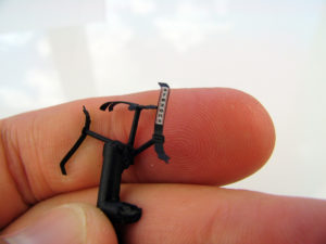
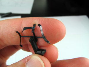
As the seatbelts are etched in a silver metal, the belts can normally be replicated by either paint, or by scraping away the paint with a knife. Looking at the reference included in the instructions for this kit, it appeared that the buckles and other fittings were a much darker metal colour. Tamiya X10 (gun metal) was used to replicate this.
2.7 – Cockpit Parts
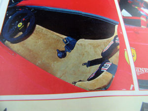
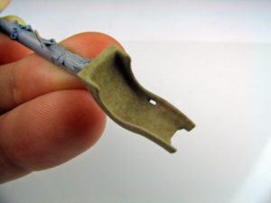
A unique feature of many Ferrari designs (including the F189) is the use of a suede leather seat. The most accurate match for this colour is Tamiya XF57 ‘Buff’ (as shown), however with a little experimentation, a more convincing finish is possible.
2.7 – Cockpit Parts
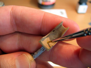
For this task, I like to use Humbrol enamels as it is possible to lift the thick pigment from the bottom of the tin and get a very matt finish but reasonably long work time before the paint dries. Using Humbrol #148 as a base, and adding small amounts of #110 and #62,
an old, stiff brush is used to dab the different colours over the base coat.
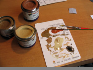
2.7 – Cockpit Parts
As the paint begins to dry, the bristles of the brush will stiffen and dabbing the end of the brush into the setting paint will leave a subtle texture, as well as blending in the different colours. If the contrast between the colours is too severe, the seat can be given a ‘dry-brush’ with #148 using the techniques in Section 2.10.
2.7 – Cockpit Parts
The completed seat ready for seat belts.
2.7 – Cockpit Parts
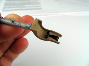
To complete the seat, small areas are brush-painted with gloss clear, the decals are applied, and a final coat of matt clear finishes the suede areas. Finally, the belts can be attached and the finished part is set aside for final assembly.
2.8 – Wheels and tyres
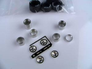
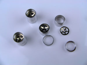
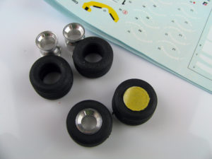
The wheels for the F189 are represented by a combination of turned and photo-etched metal parts.
2.8 – Wheels and tyres
Simple assembly of the components is all that is required for a highly accurate representation. The three parts of the wheels placed together and then held tightly as thin superglue is dabbed onto to the join. The glue will naturally be drawn into the gap by capillary action, forming a strong bond.
2.8 – Wheels and tyres
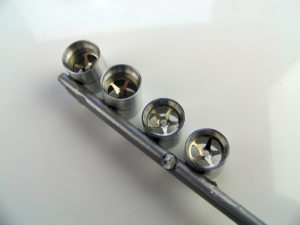
The wheels are then mounted on a plastic stick for priming and painting.
2.8 – Wheels and tyres
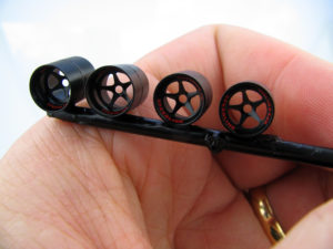
As decals need to be applied to the rims, the wheels are painted in gloss black before the decals and a light overspray of semi-gloss clear.
2.8 – Wheels and tyres
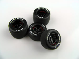
The tyres included in this kit are of Tameo Kits latest design and include pre-printed logos, low sheen side walls and smooth, matt road contact surfaces. Nothing is left for the modeller to do other than slide the tires onto the wheels and set them aside for final assembly. As the tires can attract dust, it is suggested that the tires be given a light wash under running water prior to attachment on the model.
2.8 – Wheels and tyres
Later chapters of this build diary will outline techniques to decal and finish older style tires. To ensure a consistent result, this will involve masking the wheel rim, painting the side-wall in gloss clear, applying the decal and then spraying a flat clear overcoat.
2.9 – Suspensions
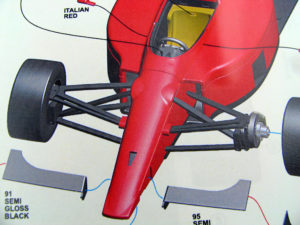
Another feature of Formula 1 cars of the 80’s and 90’s was the fine metal wishbone and tie-rods forming the suspension system.
In 1/43, these parts are very effectively replicated in photo-etch metal, being included on a separate sheet of slightly thicker metal.
2.9 – Suspensions
The mounting points for the suspension are drilled into the body before painting. Check the photo-etch parts to determine if the attachment hole should be drilled straight into the body or on an angle. For example, on this kit, because the back of the front wishbones attach inside the sidepod, the suspension parts have helpfully been designed with the pins on an angle so the matching attachment hole can also be drilled on an angle. Typically a 0.5mm drill bit is ideal for drilling these holes. The holes can be cleaned out with the same drill bit each time the body is painted and sanded to remove any paint build-up.
2.9 – Suspensions
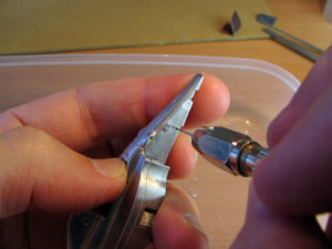
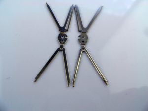
A result of the manufacturing process is that the photo-etch suspension arms have a slightly squared profile. After painting, these parts look very realistic, however modellers may wish to lightly file the edges of the arms to give them a more rounded profile. On the left is the part as it comes in the kit, the right has been filed to the rounded profile.
2.9 – Suspensions
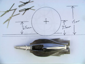
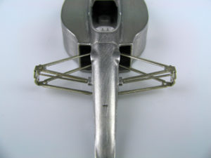
The suspension arms should then be bent to shape prior to painting. The body and undertray are screwed together and placed on a flat surface. The diameter of the tires should also be checked and an appropriate ride height determined. As the tires for this model have a 15mm diameter and there
should have a ride height of approximately 1mm, the suspension will be set so the axle is 6.5mm above the table top.
2.9 – Suspensions
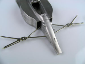
Suspension parts can be bent to shape easily, however if the parts are bent back and forwards they will quickly break. To minimise bending, I firstly press the lower wishbone into the body.
2.9 – Suspensions
The upright can then be folded up to the angle required. This is usually vertical, but for some circuits, the front wheels carry a distinct camber (usually tilting in towards the car at the top). Depending on preference, it may be easiest to remove the parts from the model to bend them, however constant test fitting is important to ensure the bend is made to the correct angle.
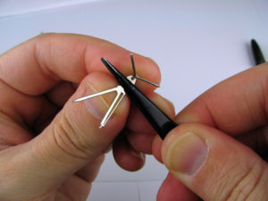
2.9 – Suspensions
With the ride height confirmed (sometimes easier if the axle part is added to the upright), the upper wishbone can be folded over and pressed into the body.

2.9 – Suspensions
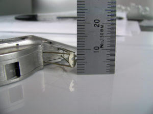
Double check the ride height again. Thankfully it looks to be close to the desired 6.5mm.
2.9 – Suspensions
The front of the car with both wishbone parts in place.
2.9 – Suspensions
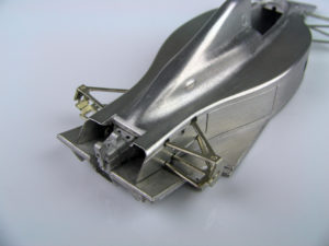
The rear suspension is fitted in a similar way, however because some of the elements fit through the body and into the transmission, the cast metal transmission was temporarily fitted to check everything aligns. Again, the ride height is confirmed and the parts removed for painting.
2.9 – Suspensions
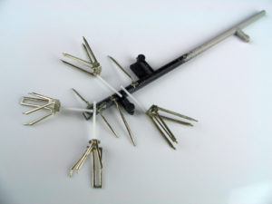
All suspension parts mounted for painting.
2.9 – Suspensions
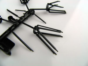
Spray a coat of clear metal primer followed by a thin coat of semi gloss black to give the parts a realistic, anodised metal look. Brakes and cooling ducts are discussed in section 2.11.
2.10 – Other sub-assemblies
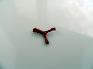
A number of other smaller components of the car should also be cleaned and prepared prior to painting. As the process of sanding and filing generates an amount of dust and shavings, it is best to complete all of these steps before cleaning your work area and starting to paint. Wing mirrors and any other parts that are to be painted in the same colour as the main body, should be prepared at this time. With this particular kit, because the casting attachment points were at the point where the mirrors will attach to the body, I decided to simply sand the parts and paint them still attached to the casting tree. Once painted, they will be cut off with a sharp knife and fitted to the body.
2.10 – Other sub-assemblies
Brakes are built from a combination of cast metal, turned and etched parts.
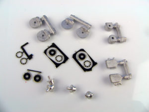
2.10 – Other sub-assemblies
Those parts that need to remain silver are put aside to be added after painting. The remaining parts are primed and sprayed in matt black.
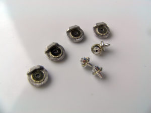
2.10 – Other sub-assemblies
The callipers (Tamiya X31) and brake disk (Tamiya X10) surfaces are painted by hand and decals applied to the callipers. Turned and etched parts are then added to the complete unit.
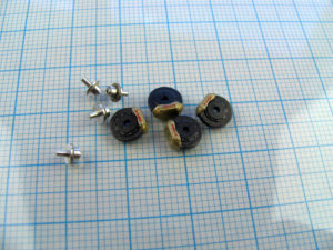
2.10 – Other sub-assemblies
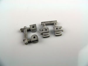
The brake ducts for this car are manufactured with an opening in the end. Modellers may wish to open this further using techniques outlined in section 2.5. The kit parts are shown in this picture and are prepared using the techniques discussed in Section 2.2.
2.10 – Other sub-assemblies
The brake ducts on the real car are made from carbon fibre. Modellers can choose to either paint the part in a low sheen black, or use surplus carbon fibre decals from the kit (possibly from the second decal sheet included in the kit) to add the carbon weave pattern to the parts. If decals are to be used, masking tape patterns can be made of the parts and then used to cut decals to the required size.
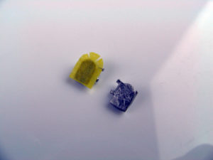
2.10 – Other sub-assemblies
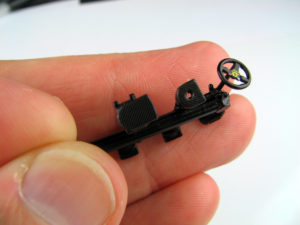
Using the templates prepared earlier, small sections of carbon fibre decal are cut from the spare decal sheet. Decal softener was used to help the decals attach to the curved surface of the parts (see Section 2.15 for further explanation). The accompanying picture shows the parts immediately following decal application, but prior to a final semi-gloss clear coat.
2.10 – Other sub-assemblies
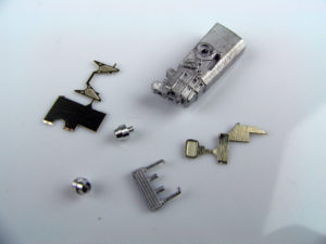
The transmission is represented by a highly detailed cast metal part and a number of etched and turned pieces.
2.10 – Other sub-assemblies
The instructions suggest the transmission part is painted in gun metal. This part is largely hidden and gun metal is an excellent match for the real part, so simply spraying the part with this colour is a good way to go. For something with a little more colour variation, a few layers of colour can be used to give a slightly more interesting finish. The first step is to paint the transmission part with a very thin coat of dark grey to darken the part, yet still allow some of the metallic look to show through.
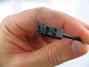
2.10 – Other sub-assemblies
The surface of the transmission was then dry-brushed with metallic grey. The dry-brushing process involves using a wide, flat brush, dipped in metallic grey enamel paint, then wiped on a cloth to remove most of the paint. Test by rubbing the brush on a piece of white paper – it should only leave a faint smudge of colour. Once its ready, lightly brush it over the part. This should leave small amounts of paint on the raised surfaces, highlighting the cast detail.
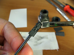
2.10 – Other sub-assemblies
The turned metal parts to link with the half shafts were attached and the whole part was given a light overspray with clear smoke.
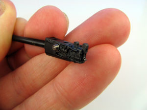
2.10 – Other sub-assemblies
Detail parts and decals can be added after painting.The completed part is dark and highly mechanical, making a great contrast to the smooth lines and high paint of the body parts.
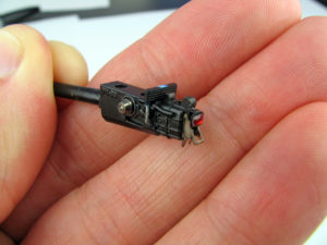
2.11 – Vac-formed parts
The windshield surrounding the cockpit is one of the more challenging aspects of the F189 kit. This feature is represented with vacuum-formed plastic and is very thin and accurate. Given the need to trim this part accurately as well as minimising handling of the finished body part, it is preferable to trim this part to a good fit now so it can be added easily after painting.
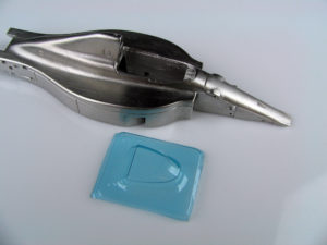
2.11 – Vac-formed parts
So there is a good section of surrounding plastic to hold for at least half the process, start by trimming one side of the part – in this case the lower half. Sharp scissors are used to cut away the bulk of the surrounding plastic and slowly get closer to the intended shape.
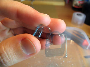
2.11 – Vac-formed parts
Because this windshield part had such sharp definition at the edges, it is possible to sand at these corners with #1000 sandpaper until the excess plastic is separated from the body.
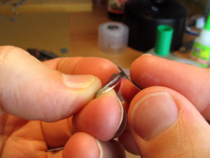
2.11 – Vac-formed parts
This is a little time consuming, but ensures that the part is accurately separated from the surrounding sheet plastic. Throughout this process, be very careful with the angle of the sandpaper to ensure that the actual windshield is not scratched. Final smoothing of the edge can be completed with fine sandpaper (in this case #8000 grade micromesh).
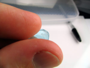
2.11 – Vac-formed parts
The part is checked against the body of the car to highlight areas where further trimming is needed.
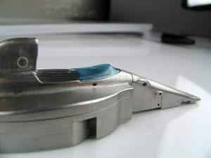
2.11 – Vac-formed parts
Process then repeated on the upper side to complete the part.
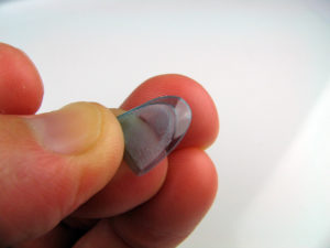
2.11 – Vac-formed parts
Wrapping micromesh around a paint brush handle can help to get an even, rounded profile on the upper edge of the part.
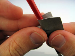
2.11 – Vac-formed parts
Check the part one last time to confirm an accurate fit, and the windscreen can be set aside until final assembly. A final polish with Tamiya Compound can assist in clearing any final imperfections and this will be completed immediately prior to attachment of the part.
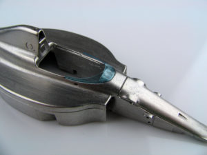
2.12 – Floor
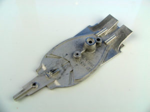
While it is largely covered in black paint and then placed under the colourful parts of the model, the floor remains a large component of a 1/43 model and it is worth spending a little time to ensure the part looks good. The accompanying picture shows the floor after the cleaning and fitting work described in Section 2.4
2.12 – Floor
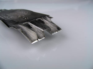
The edges of the defuser can be thinned to scale thickness using the techniques outlined in Section 2.5. The simplicity of the F189’s design makes this an easier exercise and a file and hobby knife can quickly shave the parts to a thinner appearance.
2.12 – Floor
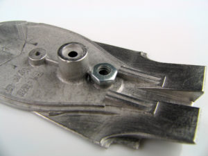
To complete this part, a small hole was drilled in the floor and a nut super-glued in place. This will allow the model to be attached firmly to a display base after assembly. The floor will now be primed, painted in gloss black and decaled following the steps outlined in the remainder of this chapter.
2.13 – Mounting parts for painting
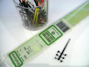
To facilitate handling during painting, all parts need to be attached to some form of handle. This needs to be both sufficiently well attached to survive the painting process, but also easy to remove prior to assembly. Superglue is very good for attachment as it has a good hold, but is brittle enough to be readily removed later. Short sections of sprue from plastic model kits are retained to be used as the ‘trunks’ of the parts ‘tree’. Larger parts such as the seat are simply glued to the sections of sprue, however smaller components are first glued to short sections of thin plastic rod and then attached. For some photo-etch parts, a small section of the surrounding frame is retained for mounting.
2.13 – Mounting parts for painting
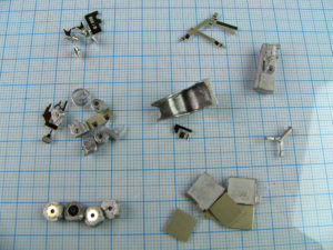
On each part, a contact or hidden section of the part needs to be identified for the attachment of short sections of plastic. These are left over sections of plastic kit sprues and thinner sections of plastic strip for small parts. Parts are grouped according to final colour (as shown in the picture) to ease painting.
2.13 – Mounting parts for painting
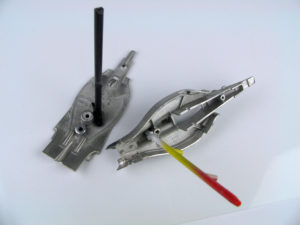
For major parts of the kit (body and floor), it is important to identify an area were a large contact point is possible to minimise the risk of the part breaking free during painting. This relies on the parts have a strong bond with the mounting stick. It is much better to check the part – even if it means breaking the attachment now – than have the part break off when wet with paint or in the middle of decal application.
2.14 – Painting body parts
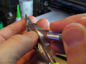
One final step prior to assembly is to check the panel lines in the body. When using a spray can for painting, it is easy for these lines to fill in a little as the layers of paint are sprayed and sanded. To add further definition to the cast detail, a knife can be
used to cut into the metal in the bottom of the panel line, deepening and sharpening it. About 2-3 passes over the line, each with slightly increased pressure, is sufficient to ensure that carefully sprayed paint will not clog the detail.
2.14 – Painting body parts
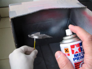
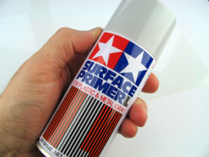
With all the preparation completed, its time to start painting. To maximise paint adhesion and limit the risk of paint chipping during assembly and handling, the metal parts are initially given a light spray with metal primer. Tamiya clear metal primer is used here, but any ‘etch’ primer from a hardware or auto-parts store can be used. As with subsequent layers, the metal primer coat should be sprayed from a distance of about 30cm and not allowed to build up too thickly on the parts.
2.14 – Painting body parts
Next, a thin coat of Tamiya grey primer is sprayed over all parts.
2.14 – Painting body parts
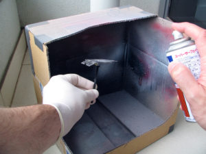
Because I do not have space at home to set up a permanent spray booth, I use a section of cardboard box to catch overspray. The model part is held inside the box in one hand and the spray can is held in the other. A latex glove can be worn to prevent too much of the spray paint from ending up on your hand.
2.14 – Painting body parts
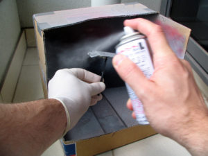
The model should be painted in a still, dust-free environment with plenty of ventilation. Ideally this is outside on a day with little or no wind and very low humidity. Temperature can also be a factor and spraying in extreme hot or cold can give undesirable results. Given I need to paint outside, this sometimes means waiting a few days for appropriate conditions. Similar to the metal primer coat, the grey primer is best sprayed in even passes over the model parts from a distance of 20cm – 30cm.
2.14 – Painting body parts
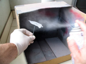
Always start the paint spray before the nozzle is aimed at the model, and continue the spray after the jet of paint has completely passed over the model. When spraying all but the final coats, it is very important to keep the coats thin. The spray primer is essentially heavily diluted filler and if the paint is sprayed thick enough to allow it to pool on the surface of the model, it will tend to accumulate in and around detail (panel lines in particular) and soften the detail. Each coat should build on the surface of the model as a gentle mist – much like the way steam builds on a bathroom mirror when having a hot shower. Painting is like getting just enough steam so the mirror becomes opaque, but not enough so the water forms into droplets and runs from the surface.
2.14 – Painting body parts
With the spraying complete, the part is set aside to dry. After several hours, the primer should be largely dry and the surface can be inspected. If sections of the part have not received an even cover of paint, respray those sections until appropriate cover is achieved. Once a uniform grey surface is achieved, any minor surface imperfections can be readily identified. These sections should be repaired before proceeding further with painting.
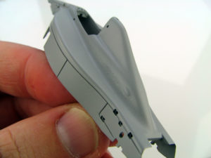
2.14 – Painting body parts
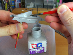
For most minor scratches or imperfections, Tamiya surfacer can be applied over the problem areas with a brush (as shown in the accompanying picture). This product is essentially a thick version of the spray primer and is halfway between the spray and traditional putty. It is a helpful product to correct small surface imperfections without the need for repeated spraying of primer and the consequential build-up of paint. More significant gaps may need filling with either White Stuff filler, or 2 part putty. This will be demonstrated in later chapters of this manual.
2.14 – Painting body parts
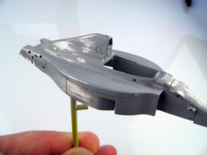
Once the surfacer and filler have had sufficient time to fully cure, the body can be sanded back to a smooth finish. Initially #600 grit sandpaper is used for spot sanding on the areas of filler, then a finer, #1000 grit sandpaper is used over the whole body. In this process, it may be necessary to sand right back to the bare metal to ensure a smooth surface.
2.14 – Painting body parts
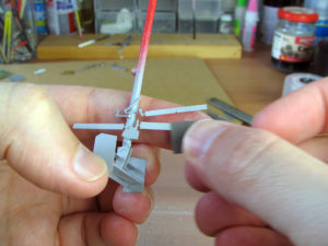
For some of the smaller detail parts, the contact point with the painting ‘tree’ can be quite small and potentially weak. For these parts, it may be necessary to both hold the parts tree, and also support the part with a finger while sanding. This should avoid the pressure of the sandpaper breaking the part free. Thankfully the parts are generally small and light, so this isn’t as much of a juggle as it sounds.
2.14 – Painting body parts
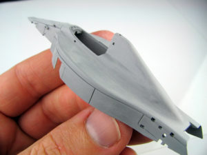
A further one or two light coats of grey primer can be applied to ensure that the filling process has successfully repaired any imperfections in the body. The accompanying picture shows the body after sanding, prior to the final primer coat. At this point the sanding should not cut back to the metal. Rather, the focus should be on smoothing the surface and ensuring an even base for the subsequent coats. Each time the body is sanded, it should be carefully washed with detergent and a toothbrush to remove all dust from the sanding and ensure the paint can adhere properly to the surface of the model.
2.14 – Painting body parts
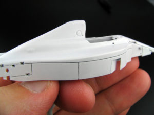
Following a light sand with #1000 paper, two thin coats of white primer are applied. The white surface is necessary as the red paint is slightly transparent and an even white (or pink) base is needed to ensure a vibrant colour. Once cured, the white primer is sanded (or more accurately, polished) to a very smooth finish with #1200 sandpaper in preparation for colour.
2.14 – Painting body parts
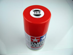
Tamiya’s TS8 spray is an excellent match for the Ferrari colour used in 1989. Consistent with the approach of assembling this kit using simple tools and materials, the paint will be sprayed straight from the can. Airbrushing the colour allows greater control of the paint flow, but obviously requires significant investment. Aiming to create a thin, even layer with each coat, the body parts will be given three coats of TS8. About 30 minutes is allowed between each coat to allow the paint to settle and much of the gas and solvents to escape. These base colour coats should also provide good coverage of all parts of the car. Between coats, it is advisable to check the paint coverage under different lights (sunlight, shadow, artificial light etc) as each may highlight sections where the paint is too thin leaving an inconsistent colour.
2.14 – Painting body parts
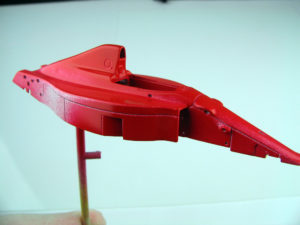
The accompanying photo shows the model after the very first sprays of red, aimed to provide some initial coverage in the areas that can be more difficult to paint (inside airbox, radiators, cockpit etc). It is also important to plan the sequence of passes with the spray can to ensure these tricky sections receive adequate cover before the surrounding areas have too much paint build up. It is advisable to paint the wing mirrors at this time as well. These are the only other part of the F189 to be painted in the main body colour, but it is still important to ensure all layers are the same so the painted part will have a consistent colour and finish.
2.14 – Painting body parts
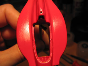
The body is then left to cure for up to a week depending on temperature and humidity. Once the paint is hard (it can be tested by trying to mark the surface with a finger nail), it is given a light sand with #800 sandpaper. This should aim to remove any ‘orange peel’ texture in the surface of the paint and will leave the surface look semi-gloss to matt, but without any visible scratches. The ‘orange peel’ is visible in the accompanying picture.
2.14 – Painting body parts
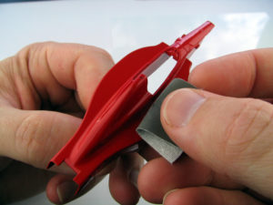
The sanding is carried out with a small section of #800 micromesh. This should just gently buff the surface of the model. If scratches are visible, the sandpaper is too harsh and a finer grade should be used. Similarly if any ‘orange peel’ remains visible in the surface, the sandpaper is not sufficiently rough. If at any point the sanding cuts through the paint surface to the primer underneath, the model should be resprayed with TS8 and the sanding restarted.
2.14 – Painting body parts
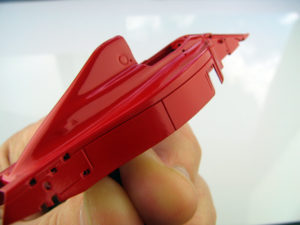
A final, slightly heavier coat of TS8 is then sprayed and allowed to cure prior to decal application. Sprayed onto the sanded surface, this coat should settle to a smooth, high gloss surface. Throughout the painting process, builders should focus on keeping the paint coats thin and even. It is always easier to return later to spray extra coats than it is to remove paint that has pooled up around detail. The surface of the model will be defined by the quality of the clear coat, so all that is required from the TS8 layers is an even, consistent application of colour.
2.14 – Painting body parts
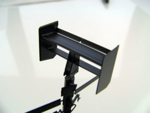
The floor and wing parts are primed in the same sequence as the body parts.
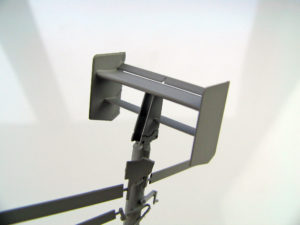
2.14 – Painting body parts
These parts were then given a light spray of matt black. The matt paint is used because it gives a more even coverage and is less inclined to pool in and around the fine detail areas.
2.14 – Painting body parts
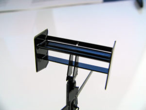
Once the matt black coat is dry, a thin coat of gloss black is sprayed to give a gloss surface for the carbon fibre decals to follow. The important thing with these undercoats is to ensure an even coverage of black and a smooth surface for the decals to follow. The final surface will be provided by the clear-coat over the decals, so a mirror gloss surface is not necessary.
2.15 – Decals
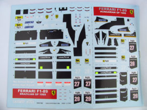
With the paint fully cured and checked for any imperfections, it is time to move to one of the most enjoyable aspects of model building… Applying decals! Tameo Kits have helpfully included 2 sheets of decals in this kit so there is an opportunity to experiment a little to perfect your techniques. To ensure they remain undamaged, the second set of decals should be separated and put in a separate location unless or until required.
2.15 – Decals
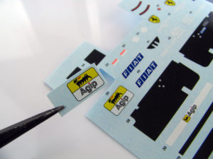
As all decals behave slightly differently (different stickiness, flexibility etc), it is advisable to test a decal or two prior to starting on the actual model. The race number for the driver not being modelled is often a good decal to use. Following the steps below and applying this decal to any gloss surface will help to build confidence before starting on the model. Turning to the actual model, the builder can essentially apply the decals in any order they choose. Having determined to start with the large ‘Agip’ marking on the sidepod of the F189, the marking is identified on the decal sheet and cut clear with sharp scissors. Be careful during this process not to damage surrounding decals, either by cutting them or scratching the surface of the decal with the tip of the scissor blades.
2.15 – Decals
The decal should then be soaked in a tray of water to soften the glue and release the decal from the backing paper. The water should be at or slightly above room temperature (20C – 40C) but no warmer. Higher temperature water will release the decal quicker, but risks softening the decal to the point where it is difficult to work with. Typically the decal will need to be soaked for about 20-30 seconds, though larger markings may take a little longer.
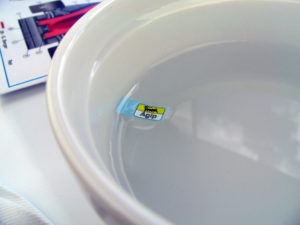
2.15 – Decals
After 20-30 seconds, the decal should be removed from the water regardless and placed on a piece of tissue or cloth. Even if the decal has not yet released from the paper, the residual water will eventually soak through. If the marking has not released in 10 seconds, it can be dipped in the water once again. If the decal is left to soak for too long, it may completely release from the paper. In this situation, the paper will typically sink and leave the decal floating on the water surface. The easiest solution is to lift the paper with tweezers and gently lift the paper up under the decal and remove both from the water together. Attempting to retrieve the decal with tweezers will almost certainly result in the decal folding around the tweezers and becoming difficult to work with.
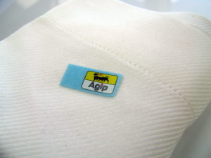
2.15 – Decals
While the decal is soaking, a small paintbrush can be used to put some small droplets of water on the surface of the model where the decal is to be applied. This will stop the decal from drying in place too quickly, allowing the modeller some time to position the decal. For decals on complex curves, some decal softener may also be added to the area where the marking will be applied.
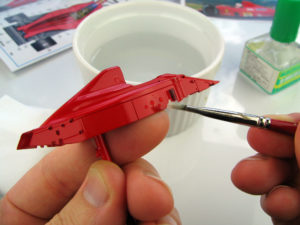
2.15 – Decals
Holding the body part in one hand, the decal paper can be placed on the side of a finger. Tweezers will be used to position the marking. It’s important at this time to have all required tools readily at hand in case they are needed quickly. This will include a paint brush to add water if the decal is sticking to the model too quickly, a piece of cloth to dry the decal, tweezers, decal softener (if required) and a gentle heat source (a desk lamp is perfect).
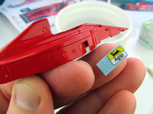
2.15 – Decals
Holding the edge of the decals with tweezers, it can be lifted from the backing paper and slid into place on the model. Take care to quickly check the alignment of the marking from every angle to ensure it is correctly positioned and square. Reference photographs and the diagram on the instruction sheet are useful for this process.
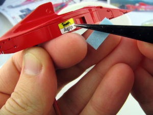
2.15 – Decals
With the decal correctly positioned, a brush can be used to gently press the decal onto the model. Start in the middle and start to gently ‘paint’ the surface with a brush moistened with water. If the decal moves on the surface of the model, quickly reposition it and hold under a lamp for a few seconds to start the glue drying. The intention is to press the decal down onto the model and remove any water or air bubbles that may be under the marking. Heat from a lamp, or gentle pressure from the brush or a finger can help the marking adhere to the model.
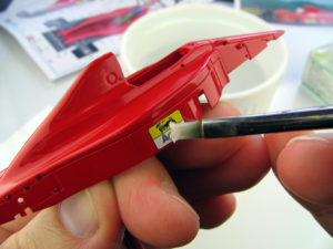
2.15 – Decals
If there are sections where the decal is not adhering to the model of if it needs to be stretched over three dimensional curves, a little decal softener, or heat can be applied to soften the decal. Gunze softener is a relatively gentle softener and this allows the extent of ‘softening’ to be carefully controlled. Caution is still advised in using these softeners as there is the potential for the decal to melt if the softener is left on too long. This is discussed further below.
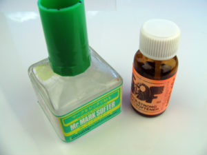
2.15 – Decals
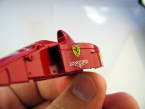
Decal softener is also useful where a decal must be applied across a panel line. Due to the layout of marking on the F189, the only area where this is a consideration is the Ferrari logos on the sidepod. In this situation, softener can be useful to ensure the decal conforms to the recess. The decal is applied and pressed down across the panel line as outlined above. Softener is then painted into the panel line at either end of the decal and allowed to flow along the groove in under the decal.
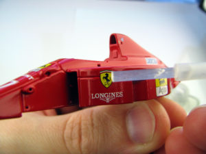
2.15 – Decals
After a short period (perhaps 30 seconds), the decal bridging the panel line will become very soft and can be pressed into the recess with a moist paint brush. Depending on preference, a fresh scalpel blade can be used to carefully cut the decal in the panel line, giving the impression that the parts actually separate at the line.
2.15 – Decals
With all body markings applied, the parts are ready for clear-coating. Some decals (such as carbon fibre within the cockpit) are left off until after this final coat is applied to avoid the weave pattern being lost under the coats of paint. At this point it is strongly advised to double check two things. Firstly, that all markings have been applied. Start at the front of the car and methodically confirm that everything that should be on the model is on the model. Secondly, make certain that all decals are square and correctly positioned. Because Tameo provide a second decal sheet, it is possible to remove a misaligned decal and replace at this time (again, discussed below), but this becomes much harder once clear coat has been applied.
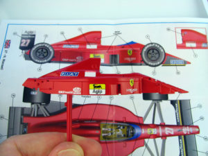
2.15 – Decals
The body part with all decals attached, prior to spraying the clear coat.
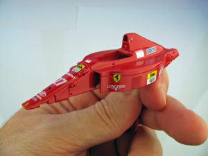
2.15 – Decals
The same technique is used to apply the decals to the wing assemblies. Here the rear wing is show with all decals applied.
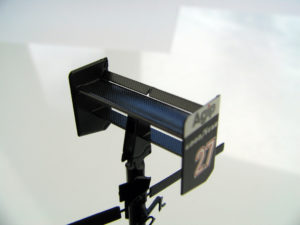
2.15 – Decals
The final elements can now be slipped into place. As I planned to give the entire rear wing a final spray with semi gloss clear, I decided not to glue the final elements, instead relying on friction and paint to hold them in place. The accompanying image shows one of the elements partially slipped into place.
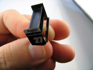
2.15 – Decals
The completed rear wing after the final semi-gloss clear coat.
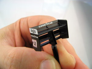
2.15 – Decals
With a little practice, decal application will become very familiar, however, decals are perhaps the most fragile element of the entire kit and there is always the prospect of something going wrong. Most commonly this will either be a result of the decal being:
– Too soft (water too hot, or too much softener). If it appears the decal is starting to soften too rapidly, quickly paint cold water on or around the decal. This will dilute the softener and may stabilise the situation. If things have gone too far, it is best to try to remove it and start again.
– Sticking to the model too quickly and not being able to be correctly positioned. Again, the best solution is to get water under the decal as soon as possible, to dilute the glue and give the modeller more time to position it.
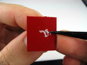
2.15 – Decals
Once a decal is damaged or softened beyond repair, it must be removed from the model. If the decal is still wet, it can sometimes be peeled off with tweezers. However, once the glue has dried, the only solution is to sand the decal off with micromesh. Be careful about the surrounding paintwork and try to only sand the decal. Once the first attempt has been cleaned up, re-spray the paint if necessary and start again with a new decal. As a final thought, never try to apply decals when you are tired or frustrated. It is a slow and time-consuming phase of assembly, but one that cannot be rushed. Start with a small number of markings (perhaps 3 or 4) and then get up and take a break. If you feel yourself rushing or making mistakes, set the model aside and come back to the model another day.
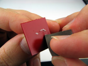
2.16 – Gloss coats
With all the decals in place, it is time to work on the final finish of the model. Adding a clear coat will help to protect the decals as well as giving a deep, showroom gloss to the model. There is a wide variety of opinions amongst modellers as to the accuracy of clear coating, with some opting not to clear coat at all, and others seeking a thick, glass smooth-finish. The real F189 featured a high-gloss finished, but does not have a visible clear-coat.
2.16 – Gloss coats
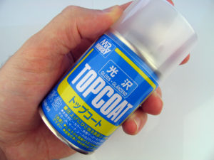
For this model, a light clear coat of Gunze Mr Topcoat will be applied. The purpose is both to protect the decals, and to blend in the step at the edge of each marking otherwise keeping the clear coat as thin as possible. Following a very similar approach to the spraying of the TS8 coats, 2-3 thin layers of clear are applied to the model about 30 mins apart. The first one – two should be very light coats, with the final being a bit thicker.
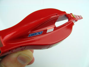
2.16 – Gloss coats
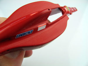
Once the clear has fully cured, it can be sanded with micromesh. This process serves two purposes, firstly removing the ‘orange peel’ texture that can build up after a couple of layers of paint, and secondly, removing some of the paint volume over the decals and reducing the step between the decal and surrounding areas. The sanding is completed with ever finer micromesh until the model is almost back to a polished gloss surface. The accompanying photo shows the model part way through the initial, heavier sanding.
2.16 – Gloss coats
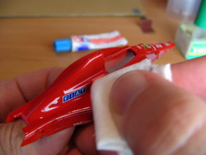
After the parts have been washed, a final coat of clear is sprayed to provide a base for polishing. Once this coat has cured, a small amount of Tamiya Polishing Compound is squeezed onto a small piece of soft cloth or tissue. The body is then polished with the compound until a high gloss is achieved.As the compound is slightly abrasive, care must be taken around raised detail as it is possible to polish through the paint if completed too vigorously. If this occurs, there is little alternative other than to mask off the section and respray the base colour, sand the edges to blend them in, and then restart the clear coating process.
2.16 – Gloss coats
Although this process is time-consuming, the end result should be a high-gloss surface on the body of the model. Having reached this point, the model is ready for final assembly.
2.17 – Final assembly
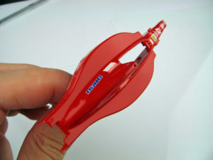
Carbon fibre decals are provided for the flat panels inside the cockpit and for the top of the monocoque above the instrument panel. The remaining black sections are initially filled in by brush – masking tape can be used to ensure a sharp edge if needed. As an alternative, short sections of carbon decal can be cut from the second decal sheet and used to mark out the start of the carbon areas – as shown in the accompanying picture.
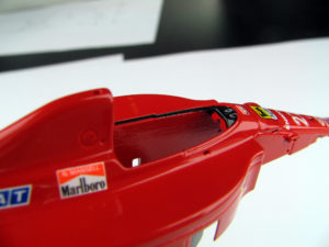
2.17 – Final assembly
Next, the remainder of the interior can be painted matt black. Following the same approach as used in the entry to the airbox, small sections of black or carbon fibre decal can be used to provide a sharp edge between areas of red and black (for example in the radiator intake and the bodywork around the transmission).
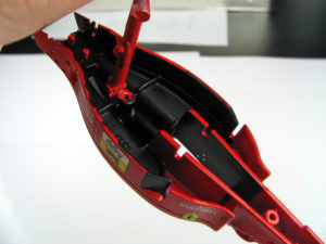
2.17 – Final assembly
Assembled radiators are added either side of the cockpit. The radiators are kept in their bare metal condition, polished and then given a light coat of smoke before installation. The smoke clear gives the impression of shadow on the parts inside the model. Polished metal could appear too bright in a section that is almost always in total shadow on the real car.
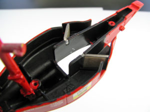
2.17 – Final assembly
The completed transmission part is attached into the rear of the body
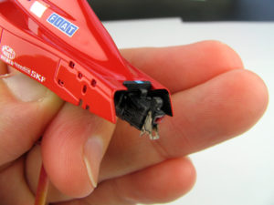
2.17 – Final assembly
The instrument panel and steering wheel are then glued in place. A small photo-etch panel is attached below the airbox to provide an attachment point for the seat belts. The belts themselves will be added after the seat is in position.
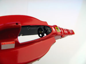
2.17 – Final assembly
With the transmission secured, the rear suspension can be added to the model. The attachment points have been helpfully recessed to give the impression the suspension arms actually extend through the body. To accentuate the effect, these recesses are painted flat black as suggested in the instructions.The suspension parts themselves are pressed into place without glue and then small dots of super-glue can be applied on the inside of the model where the photo-etch parts push through. This ensures no excess glue on the outside of the model, but relies on the ride height having been accurately set earlier in the build. The pushrod is left off at this point so that if needed, the parts can be flexed to correct the ride height once the floor has been added.
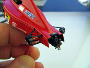
2.17 – Final assembly
L’estintore in metallo tornito è attaccato al fondo della macchina con il sedile sistemato in posizione per il test finale. Sarà fissato con la colla dopo che la carrozzeria e il fondo sono stati uniti.
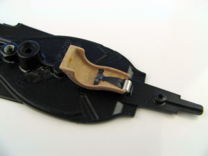
2.17 – Final assembly
The front suspension can then be added to the model. Once the paint has been scraped from the attachment points with a knife, small amounts of 2-part epoxy glue are dabbed on the attachment points and the wishbones are slipped into the body.
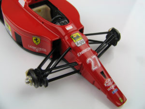
2.17 – Final assembly
Drive shafts, brake ducts and brake disks can then be added. It is important to check the fit of each component at this point and where necessary, re-drill attachment points to clear paint build-up. Also consider the sequence of the build up to ensure all parts can be easily handled.
This is particularly important with the rear suspension and drive shafts. Due to the design of this kit, the brake ducts can be glued to the suspension, and then the drive shafts pushed in through the upright, through the hole in the body and finally into the side of the transmission.
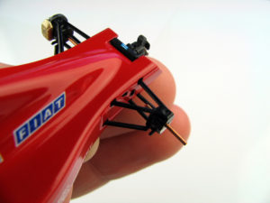
2.17 – Final assembly
Before securing the drive shafts, ensure they have been cut to a length that allows the brakes and hubs to be attached.The complete suspension assembly should be square and a perfect reflection on each side of the model.
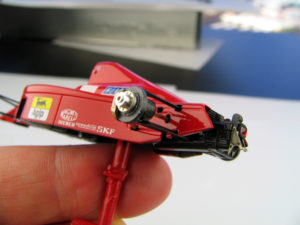
2.17 – Final assembly
To minimise risk of fingerprints or other damage on the body surface, the body and floor parts are kept attached to their painting sticks for as long as possible, however at some point it is necessary to join them so the ‘sit’ of the model can be confirmed. With all of the internal parts, and a number of the major sub-assemblies added, the parts are separated from their painting stakes by squeezing the super-glue join with some side cutters. As the glue is rather brittle, the plastic should break away readily. Holding the body part with a cloth to avoid finger prints, the two parts are positioned together and the joining screw is added.
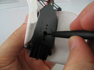
2.17 – Final assembly
The front and rear ride height can be confirmed.
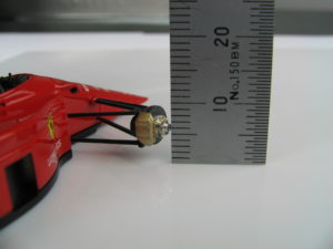
2.17 – Final assembly
The pushrods can then be installed to complete the suspension structure. Following this approach, it may be necessary to remove part of the attachment points from the pushrod where it joins the suspension near the wheel. Test-fitting will confirm if this is necessary.

2.17 – Final assembly
The wheels are attached using 2-part epoxy glue. This will dry to a very strong bond, but also allows a few minutes of valuable working time to ensure that the wheels are correctly aligned. Before gluing, it is advisable to file the attachment point of the wheel to remove the paint and ensure that the glue will bond directly to the metal. Next, a small amount of glue is applied in a ring around the turned hub. Be careful not to get any glue in the small hole in the centre of the hub as this must remain clear for the wheel nut to be inserted. The wheels are then placed onto the hubs and held in place while the glue dries. To ensure the wheels are square, vertical surfaces may be used to hold the wheels in place as the glue dries, however confirming the alignment visually may well be sufficient.
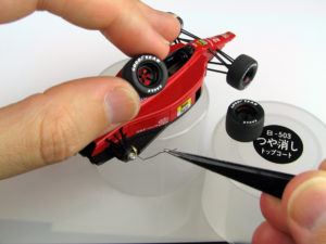
2.17 – Final assembly
With the wheels in place, the small turned wheel nuts, can be painted in semi-gloss black and glued into the hubs. Once in place, metallic grey was used to paint the wheel nut as indicated by reference material.
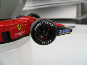
2.17 – Final assembly
The front and rear wings are attached using a similar technique to the wheels. Contact points are filed or sanded to allow a direct bond between the metal, then after completing a final test-fit, 2-part epoxy glue is applied to the contact areas and the parts are brought together.
A jig can be used to ensure the parts remain square. For the front wing this involves plastic-card to ensure an even ground clearance, at the rear, a vertical surface will ensure the part is perpendicular to the ground.
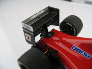
2.17 – Final assembly
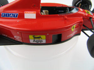
Tameo provide small, self-adhesive DZUS body fasteners in the F189 kit. Using the location guide provided on the marking plan, the fasteners are cut from the sheet and pressed into position. Other small details such as the shoulder seat belts and wing mirrors are added using tiny dots of 2-part glue. The windshield is added using white glue, mixed with a little water. This completes the build!
2.17 – Final assembly
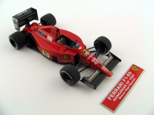
Tameo Kits’ F189 model presents a highly realistic miniature of Ferrari’s 1989 single seater. The following photographs were taken inside a light tent, as described in Section 1.11, providing even, soft lighting. For ease of handling and to assist in display, the model can be attached to a display base. The name plate is included in the kit and consists of a decal applied to a photo-etch plate.
